•
VBAT (Battery voltage)
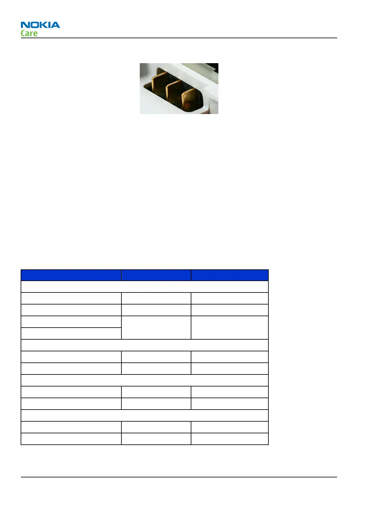
Figure 61 Blade battery connector
Charging
This phone is charged through the micro USB connector. The phone supports dedicated, host or hub chargers.
Charging is controlled by energy management, and external components are needed to protect the baseband
module against EMC, reverse polarity and transient frequency deviation.
Backup battery
When the main battery is not attached EM ASIC (N2200) goes in backup mode using back-up battery that
supplies voltage to RTC in EM ASIC (N2200).
Normal and extreme voltages
Energy management is mainly carried out in the two Application Specific Integrated Circuits (ASICs) BETTY
and AVILMA. These two circuits contains a number of regulators. In addition there are some external
regulators too.
In the table below normal and extreme voltages are shown when a BP-4L battery is used.
Table 13 Nominal voltages
Voltage Voltage [V] Condition
General Conditions
Nominal voltage 3.700
Lower extreme voltage 3.145
Higher extreme voltage
4.230(fast charging)
HW Shutdown Voltages
Vmstr+ 2.1 ± 0.1 Off to on
Vmstr- 1.9 ± 0.1 On to off
SW Shutdown Voltages
Sw shutdown 3.15 In call
Sw shutdown 3.3 In idle
Min Operating Voltage
Vcoff+ 2.9 ± 0.1 Off to on
Vcoff- 2.6 ± 0.1 On to off
RM-505; RM-506
System Module and User Interface
Page 8 –10 COMPANY CONFIDENTIAL Issue 1
Copyright © 2009 Nokia. All rights reserved.