Pin Signal I/O Engine connection Notes
5 GND - GND Ground
7 SIMDATA In/Out EM ASIC N2200 SIM1DaC Data input /
output
Charger connector and charging interface connections & electrical characteristics
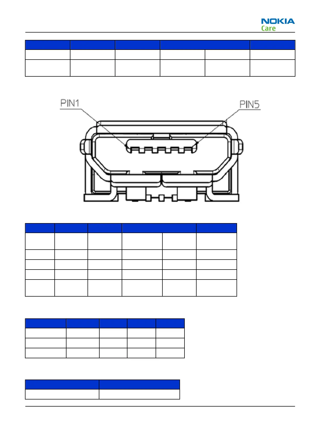
Figure 89 Charger connector
Table 15 Charging interface connections
PIN Signal I/O Engine connection Description
1 VBUS IN
D3300/
N3301 VBUS/DCIN 5V
2 D- IN/OUT D3300 DM Data minus
3 D+ IN/OUT D3300 DN Data plus
4 ID Not in use
5 ground Ground
Signal
ground
Table 16 Charging IF electrical characteristics
Description Parameter Min Max Unit
VBUS Vcharge 4.75 5.25 V
VBUS Icharge 1.8 A
D+,D-,Ground 1 A
Internal interfaces
Name of connection Component reference
Earpiece B500 on Tilt FPC
RM-505; RM-506
System Module and User Interface
Issue 1 COMPANY CONFIDENTIAL Page 8 –37
Copyright © 2009 Nokia. All rights reserved.