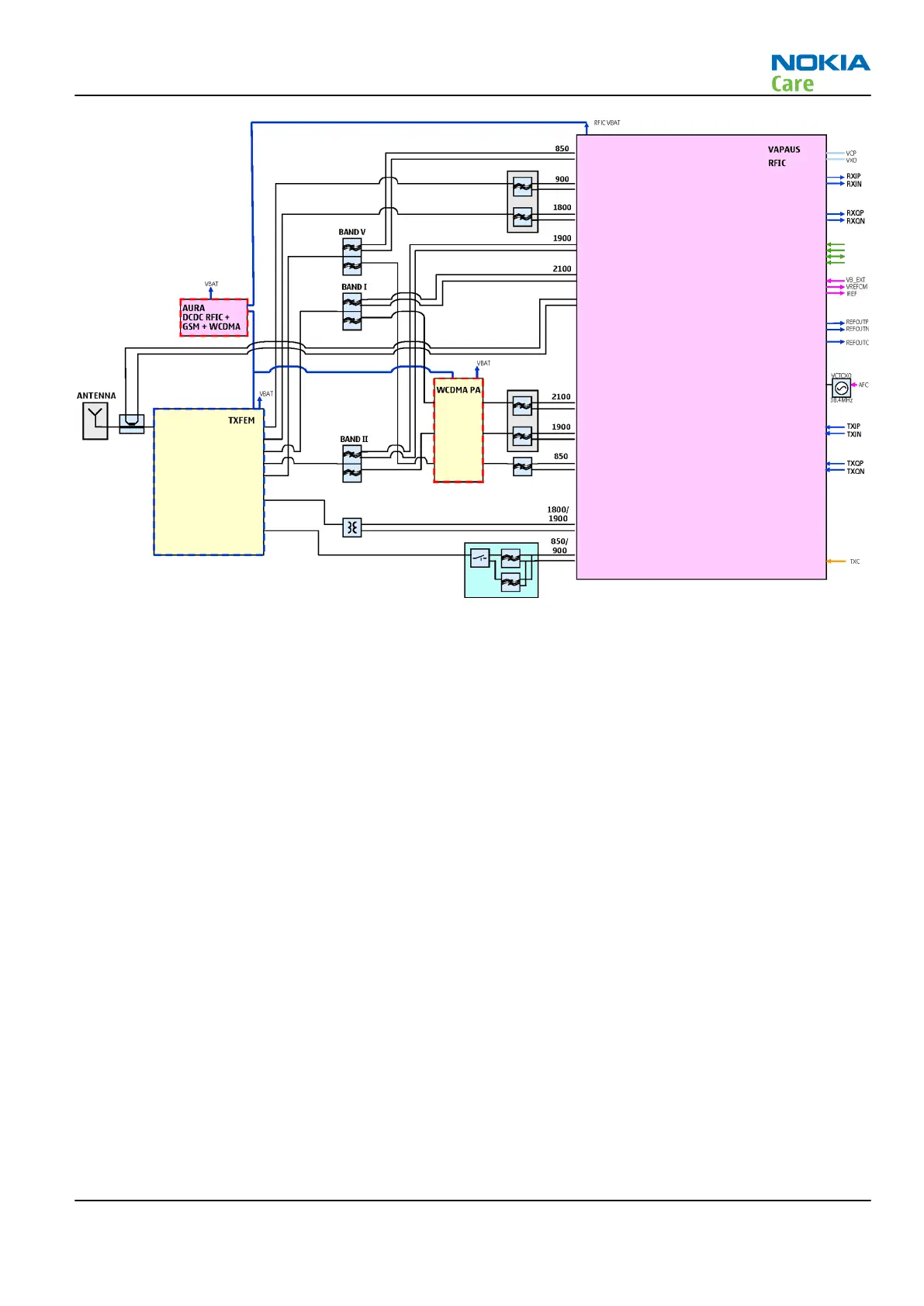
Figure 91 RF block diagram using RF ASIC N7500 (with WCDMA V/II/I)
The RF block diagram uses RF ASIC N7500 that performs the RF back-end functions of receive and transmit
function of the cellular transceiver.
Receiver (RX)
An analogue signal is received by the phone's antenna. The signal is converted to a digital signal and is then
transferred further to the baseband (eg. to the earpiece).
The receiver functions are implemented in the RF ASIC.
Signals with different frequencies take different paths, therefore being handled by different components.
The principle of GSM and WCDMA is the same.
Transmitter (TX)
The digital baseband signal (eg. from the microphone) is converted to an analogue signal, which is then
amplified and transmitted from the antenna. The frequency of this signal can be tuned to match the bandwith
of the system in use (eg. GSM900).
The transmitter functions are implemented in the RF ASIC.
Even though the GSM and WCDMA signals are sent via different components, the principles of the transmission
is the same.
RM-505; RM-506
System Module and User Interface
Issue 1 COMPANY CONFIDENTIAL Page 8 –39
Copyright © 2009 Nokia. All rights reserved.