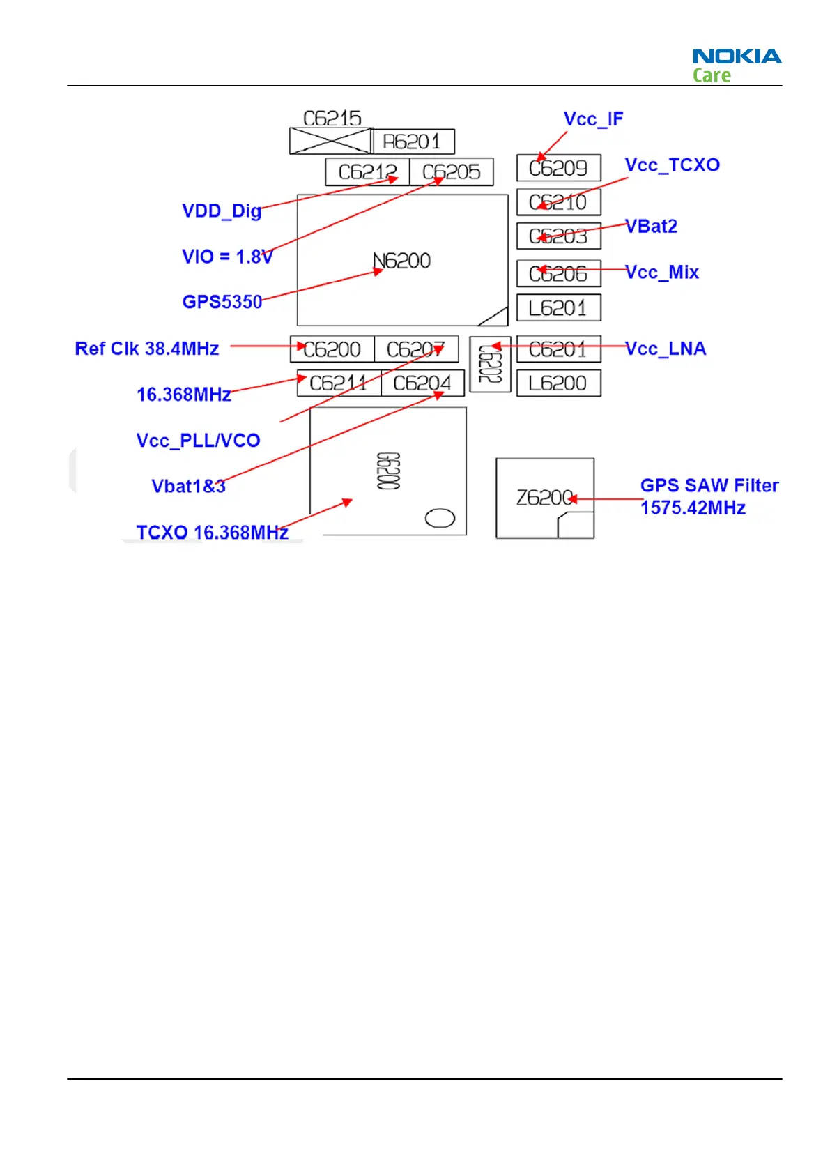
Figure 25 GPS layout and basic test points
VBat, ASIC internal LDO voltages, and clocks are available as shown in figure above. In addition to these, the
following GPS signals are available on the test points listed below:
•
U2Tx (J6200, activity on this pin indicates the GPS is operating)
GPS RF test points
The GPS test pads are located on the top side as shown in figure "GPS test pads" to perform the conducted
CW test to confirm the GPS RF path from GPS chipset to the GPS SAW filter.
J6201 is the pad to inject the CW signal
J6202, J6203 = Gnd
RM-505; RM-506
BB Troubleshooting and Manual Tuning Guide
Issue 1 COMPANY CONFIDENTIAL Page 3 –43
Copyright © 2009 Nokia. All rights reserved.