•
38.4MHz reference clock from Ahneus RF ASIC
•
32.768kHz Sleepclk
The GPS module is powered from VIO 1.8V and VBAT.
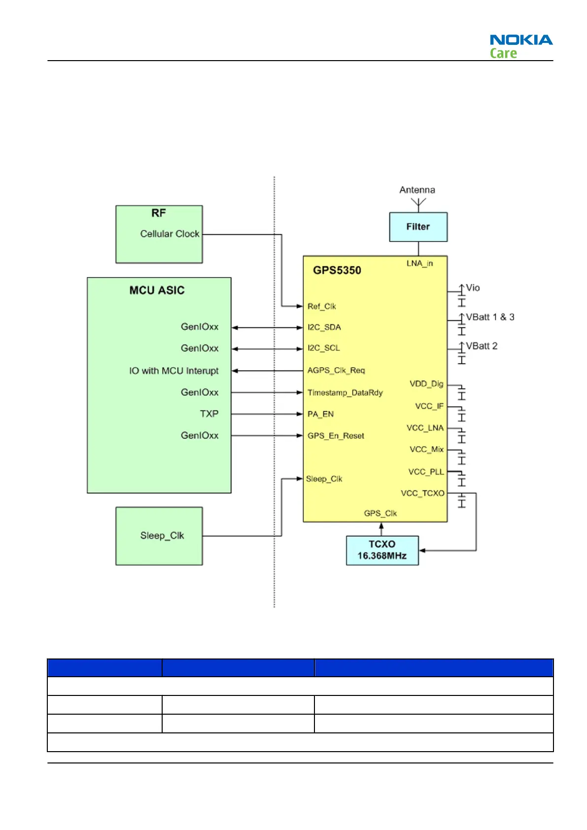
Block diagram
The following block diagram shows how the GPS module is connected to the host side.
Figure 65 Block diagram of the GPS system
Interface signals
Signal name I/O Function
RF
ANT_GPS I GPS antenna port
LNA_In I GPS ASIC RF input
Clocking
RM-505; RM-506
System Module and User Interface
Issue 1 COMPANY CONFIDENTIAL Page 8 –17
Copyright © 2009 Nokia. All rights reserved.