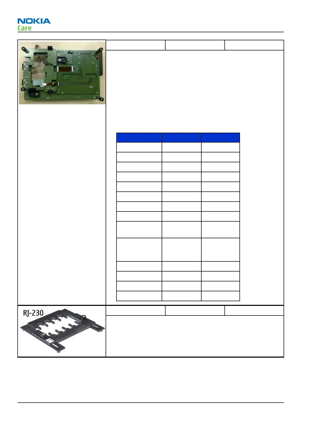
MJ-214 Module jig
MJ-214 is meant for component level troubleshooting.
The jig includes RF interface for Bluetooth, WLAN and GPS. In addition,
it has the following features:
•
Provides mechanical interface with the engine module
•
Provides galvanic connection to all needed test pads in module
•
Multiplexing between USB and FBUS media, controlled by Vusb
•
Connector for control unit
•
Access for Audio-, MMC, and USB connectors
•
Module jig attenuation values:
Band F Attenuation
GSM850 TX 824-849 0.4dB
GSM850 RX 869-894 0.4dB
EGSM900 TX 880-915 0.4dB
EGSM900 RX 935-960 0.4dB
GSM1800 TX 1710-1785 0.6dB
GSM1800 RX 1805-1880 0.6dB
GSM1900 TX 1850-1910 0.6dB
GSM1900 RX 1930-1990 0.6dB
WLAN TX
0.6dB@244
2MHz
FMTx
25.27dB@1
07.9dBm
with 22nH
WCDMA850 TX 824-849 0.4dB
WCDMA850 RX 869-894 0.4dB
WCDMA1900 TX 1850-1910 0.6dB
WCDMA1900 RX 1930-1990 0.6dB
RJ-230 Soldering jig
The jig is used for soldering and as a rework jig for the system module.
It is made of lead-free rework compatible material.
RM-505; RM-506
Service Tools and Service Concepts
Page 2 –6 COMPANY CONFIDENTIAL Issue 1
Copyright © 2009 Nokia. All rights reserved.