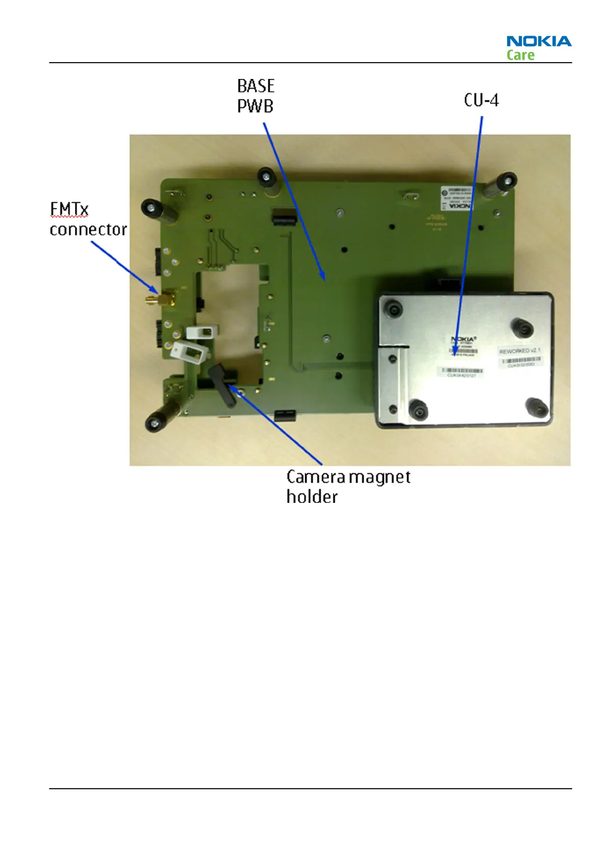
Figure 17 Module jig bottom view
Some clarifications for the above views:
•
Power key: simulate phone power key
•
IHF: simulate phone IHF
•
Mode switch: select CU-4, BSI or Local mode
•
Hinge magnet holder: simulate hinge open/close
•
Camera magnet holder: simulate camera lens cover open/close
•
UI module: Phone UI part
•
Audio FPC: Phone Audio FPC
•
SP2, SP4 and SP5: available as MJ-214 spare part
Note: Important notes:
•
Select a working phone UI part to fix in the module jig. Do not take it off unless needed. Use it
for reference for engine repair.
•
SP6 can be disassembled in order to fix UI module to it easily.
•
Use 3 phone screws to fix UI module to the module jig.
RM-505; RM-506
Service Tools and Service Concepts
Issue 1 COMPANY CONFIDENTIAL Page 2 –25
Copyright © 2009 Nokia. All rights reserved.