Setting up the C15
Setting up the C15
14 15
2. Setting up the C15
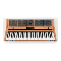
2.1 Mounting the Panel Unit
Ensure the C15 is switched o before following the next four steps:
Attach mounting brackets to Base Unit by
hanging and snapping.
Place Panel Unit on fixated mounting
brackets. There are two screws (mounting
pins) on the bottom side of the Panel Unit
fitting into corresponding holes near the
peak of each mounting bracket.
Tighten Panel Unit fixation screws in order
to lock Panel Unit in place.
Connect Base Unit and Panel Unit with the
Unit Connector Cable.
Now the C15 is ready to use and can be switched on. In order to disassemble the paired
setup, follow this protocol by applying the described four steps in reverse manner and
order. The C15 Base Unit can be used on its own as well.
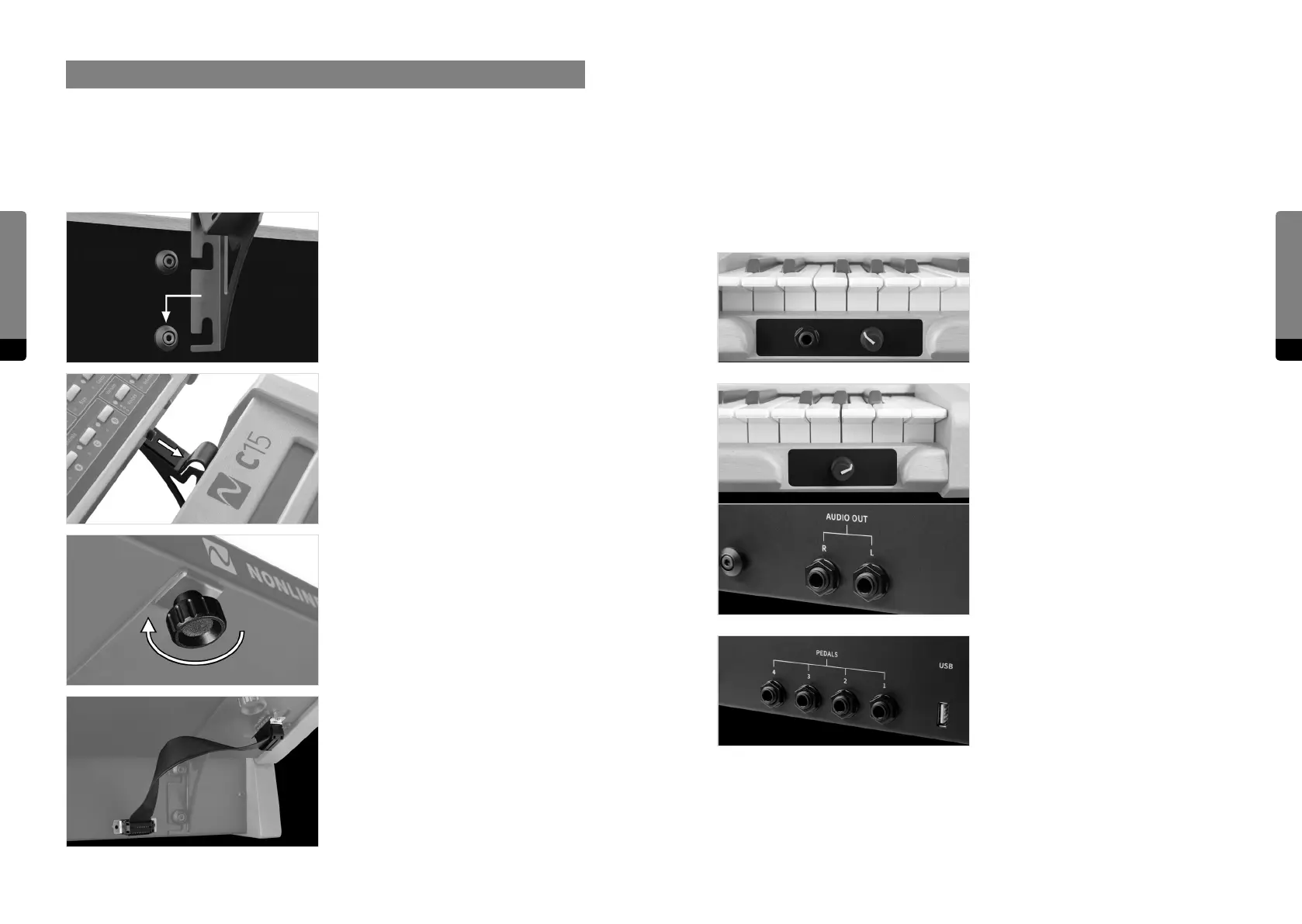
2.2 Connections
Besides the Unit Connector Cable, the following external connections are provided by the
Base Unit:
The headphone output provides a 6.3 mm
stereo headphone socket with separate,
preset-independant adjustable headphone
level.
The audio output provides two 6.3 mm
line-level audio sockets with separate,
preset-independant adjustable output
level. The signals are transformer-balanced
and ground-free, therefore in most cases a
DI-box is not necessary. Unbalanced and
balanced plugs can be connected.
Four 6.3 mm Pedal sockets are provided for
external Pedal control. In general, any key-
board controller Pedal can be connected.
Nevertheless, only continuous Pedals
allow for a nuanced performance and are
therefore recommended.