Installation
3-4
Part 1024496_06
2014 Nordson Corporation
Installation Requirements
Before installing the melter, ensure that the desired installation location
provides the required clearances, environmental conditions, and utilities.
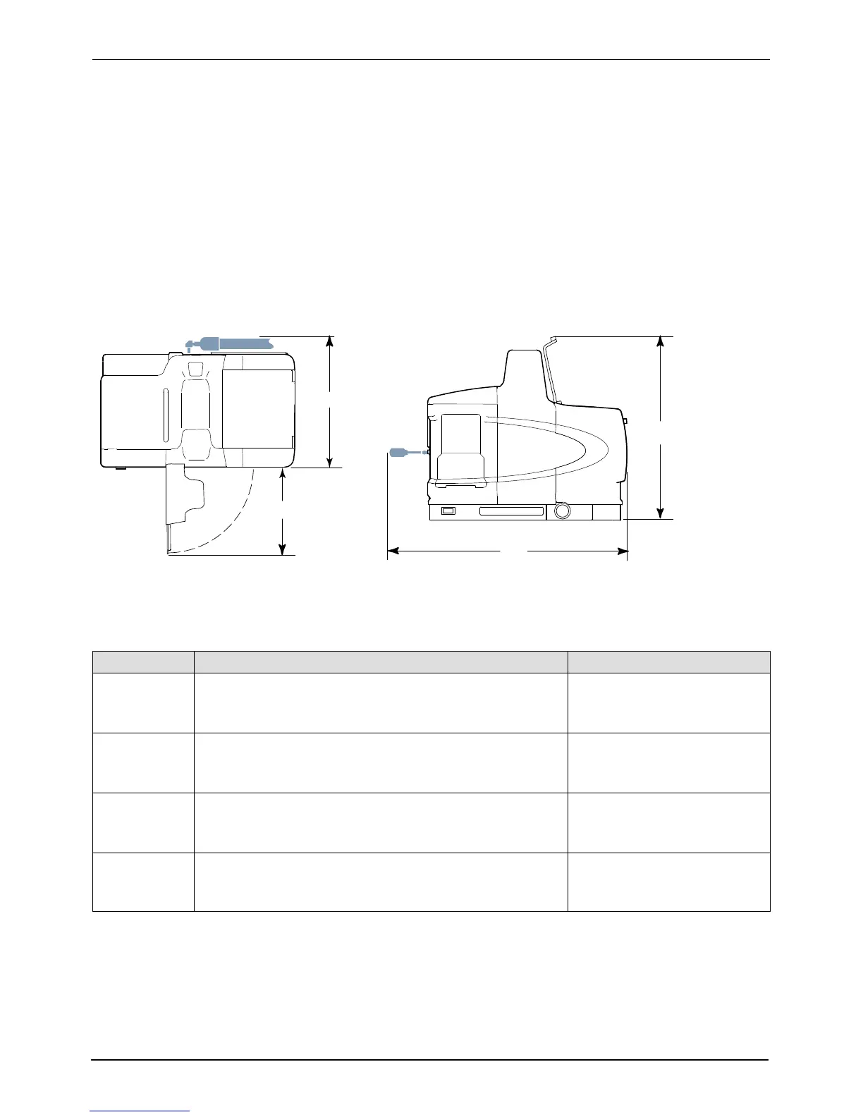
Clearances
Figure 3‐1 illustrates the minimum clearances that are required between the
melter and surrounding objects. Table 3‐1 describes each clearance.
NOTE: 400/480 volt melter clearances are provided in Appendix E.
A
B
C
D
Figure 3‐1 Minimum installation clearances (Top and side views shown)
Table 3‐1 Installation Clearances
Item Description Required Clearance
A
The distance from the outside edge of a
5
/
16
‐inch Nordson hose
to the front face of the melter when a short 90‐degree hose
fitting is used to connect the hose to the melter
P4 = 370 mm (14.5 in.)
P7 = 370 mm (14.5 in.)
P10 = 391 mm (15.4 in.)
B
The clearance required to open the pump enclosure door P4 = 243 mm (9.6 in.)
P7 = 243 mm (9.6 in.)
P10 = 268 mm (10.55 in.)
C
The distance from the melter sub‐base to the front edge of the
tank lid when the lid is at its highest point.
P4 = 502 mm (20.0 in.)
P7 = 564 mm (22.2 in.)
P10 = 656 mm (26.0 in.)
D
The clearance required on the left side of the melter to open the
electrical enclosure door or remove a hose/gun module.
P4 = 648 mm (25.5 in.)
P7 = 711 mm (28.0 in.)
P10 = 714 mm (28.1 in.)
 Loading...


