en-938821/2 2 - 15
Product Presentation
2
Select the next page. ☞
. . / . .
DAT
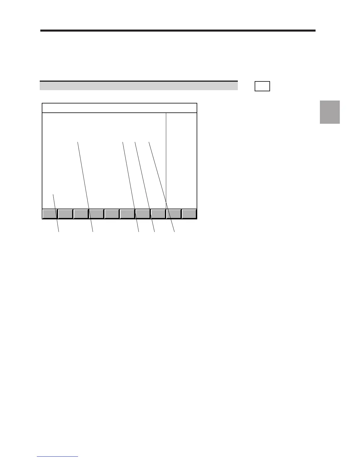
Display of the "PLC BUS HARDWARE CONFIGURATION (RACK 0)" page, for instance:
1 2 3 4 5
PLC BUS HARDWARE CONFIGURATION (RACK 0)
Address Designation File number Vers. Ident.
0 Main serial bus 204 201 857 0 $000000
0 130W power supply with optic F. 204 201 950 0 $000000
1
2
3
4
5 32 inputs board 204 201 926 0 $000A00
6 32 relayed outputs board 204 201 746 0 $000100
7
8
9
10
11
12
13
1 - Address on the serial bus:
- address 0 corresponds to the serial bus and the fibre-optic
interface on the power supply card
- addresses 1 to 4 are reserved for the machine panels
- addresses 5 to 12 are reserved for the input/output cards
2 - Card description
3 - Part number of each card
4 - Card functionality index (decimal conversion of the last character
of the identifier. For instance, if the last character is D, the
functionality index is 13)
5 - Electronic identifier of each card (this number is used to ensure
card interchangeability)
Each line of the "PLC BUS HARDWARE CONFIGURATION (RACK 0)" page gives information on a module installed
on the serial bus.
Blank lines correspond to empty slots.
When the system includes extension racks, the sign ".../..." is displayed in the bottom right-hand corner of the page.