•
•
•
•
1.
2.
a.
b.
c.
d.
3.
documentation for instructions. Before you install the DPU, make sure that the system is
disconnected from power.
5.7 Installation Instructions
This section provides detailed instructions on how to install your DPU/SuperNIC in a system.
Choose the installation instructions according to the DPU configuration you would like to use.
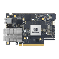
OPNs Installation Instructions
All DPUs PCIe x16 DPU/SuperNIC Installation Instructions
B3220 Model: 900-9D3B6-00CV-AA0 and
900-9D3B6-00SV-AA0
B3240 Model: 900-9D3B6-00CN-AB0 and
900-9D3B6-00SN-AB0
B3210 Model:900-9D3B6-00CC-AA0
and900-9D3B6-00SC-AA0
B3210E Model: 900-9D3B6-00CC-EA0 and
900-9D3B6-00SC-EA0
PCIe Extension Option (2x PCIe x16) Installation
Instructions
5.8 Cables and Modules
5.8.1 Networking Cable Installation
All cables can be inserted or removed with the unit powered on.
To insert a cable, press the connector into the port receptacle until the connector is firmly
seated.
Support the weight of the cable before connecting the cable to the DPU/SuperNIC. Do
this by using a cable holder or tying the cable to the rack.
Determine the correct orientation of the connector to the DPU/SuperNIC before
inserting the connector. Do not try and insert the connector upside down. This may
damage the DPU/SuperNIC.
Insert the connector into the DPU/SuperNIC . Be careful to insert the connector
straight into the cage. Do not apply any torque, up or down, to the connector cage in
the DPU/SuperNIC.
Make sure that the connector locks in place.
After inserting a cable into a port, the Green LED indicator will light when the physical
connection is established (that is, when the unit is powered on and a cable is plugged into
the port with the other end of the connector plugged into a functioning port). See
Networking Ports LEDs interface under theSupported Interfacessection.
When installing cables make sure that the latches engage.
Always install and remove cables by pushing or pulling the cable and
connector in a straight line with the DPU.