Miscellaneous Interfaces
PRELIMINARY INFORMATION
NVIDIA Jetson Orin NX DG-10931-001_v0.1 | 67
Table 12-8. UART Signal Connections
Ball Name Type Termination Description
UART[2:0]_TXD O UART Transmit: Connect to peripheral RXD pin of device
UART[2:0]_RXD I UART Receive: Connect to peripheral TXD pin of device
UART[1:0]_CTS* I UART Clear to Send: Connect to peripheral RTS pin of device
UART[1:0]_RTS* O UART Request to Send: Connect to peripheral CTS pin of device
12.4 CAN
Jetson Orin NX brings a single controlled area network (CAN) interface to the main connector.
Table 12-9. Jetson Orin NX CAN Pin Descriptions
Pin #
Module Pin
Name
Orin Signal Usage and Description
Recommended
Usage
Direction Pin Type
143 CAN_RX GP17_CAN0_DOUT CAN Receive
CAN PHY
Input CMOS – 3.3V
145 CAN_TX GP18_CAN0_DIN CAN Transmit Output CMOS – 3.3V
Notes:
1. In the Direction column, Output is from Jetson Orin NX. Input is to Jetson Orin NX. Bidir is for Bidirectional signals.
2. The direction indicated for the CAN signals are associated with that usage. The pins support GPIO functionality, so support both
input and output operation (bidirectional).
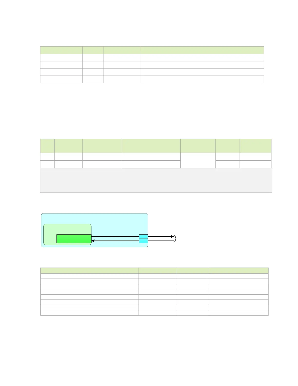
Figure 12-6. Jetson Orin NX CAN Connections
Jetson
SoC - CAN
GP17_CAN0_DOUT
GP18_CAN0_DIN
CAN_TX
CAN_RX
145
CAN
PHY
143
Table 12-10. CAN Interface Signal Routing Requirements
Max Data Rate / Frequency
Configuration / Device Organization
Via proximity (Signal via to GND return via)
Trace spacing: Microstrip / Stripline
Max Trace Length (for RX and TX only)
Max Trace Length/Delay Skew from RX to TX

 Loading...


