Clock tool example use case: Configure eMIOS to 60 MHz PLL1 with MPC5777C_264MHz
MPC5777C Clock Calculator Guide, Rev. 1, 12/2018
20 NXP Semiconductors
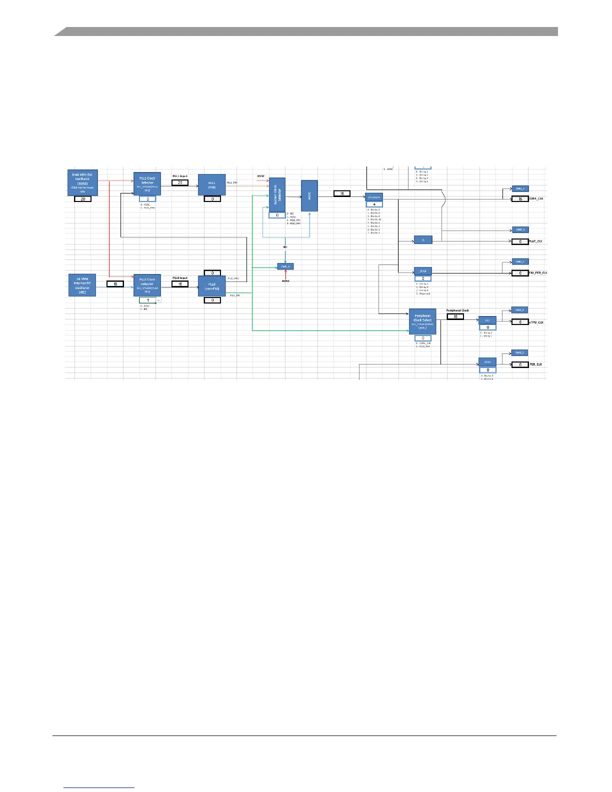
textbox explains what each available value represents. As shown in the figure, CORE_CLK, in turn, is
currently sourced from the 16 MHz IRC, divided by 1, for a final frequency of 16 MHz.
Since the only way to achieve 60 MHz is through the PLL, one of the PLLs must be configured. This
example will choose PLL1. Trace PLL1_PHI back to its own sources. PLL1 selects from either XOSC
or PLL0_PHI1 via PLL1 Clock Selector. These oscillators are the point of origin for all clock domains.
The figure below shows PER_CLK being traced back to PLL1 and then finally to the oscillators.
Figure 24. PER_CLK to oscillators
3.2.1.
Configure the oscillator
Now start going downstream, configuring from the oscillator down to PER_CLK. The external oscillator
frequency is application-dependent and can be any value between 8 MHz and 40 MHz. This tool has a
safeguard to prevent invalid values from being entered. The Figure23 shows an attempt to enter 7 MHz
to the XOSC frequency cell. A dialog box appears notifying the user that the value is not accepted when
he/she tries to click away from the cell.

 Loading...


