Chapter 11: IBM - Graphics
11-5
128
64
32
16
8
4
2
1
128
64
32
16
8
4
2
1
128
64
32
16
8
4
2
1
Byte 1
Byte 2
Byte 3
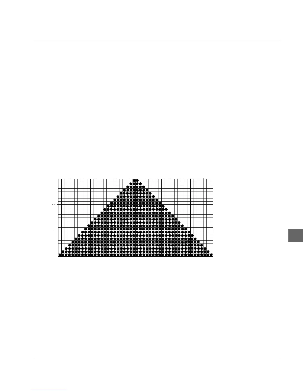
You are properly using the performance of your printer if you choo-
se one of the 24-pin modes. After selecting the required density,
you can design your graphic and convert it step by step into data
for the printer. Make sure that 24-pin graphics consist of a number
of columns each composing 3 bytes.
The variables n
1
and n
2
communicate to the printer the total number
of bytes including attribute and graphics data which follow the
command sequence ESC [ g n
1
n
2
. The total number of data bytes
consists of a mode byte m and the number of graphic bytes sent to
the printer. In the case of 24-pin graphics, the parameters n
1
and n
2
must take account of the number of graphic bytes determined from
the number of graphic columns times 3 and the attribute byte.
The second command ESC * m n
1
n
2
is only valid in Alternative Gra-
phics Mode (AGM). It corresponds precisely to the Epson com-
mand for high resolution graphics. A description of this command
and an example are to be found in Chapter 12.
Our example composes 48 columns. If the triangle is to be printed
six times one after the other, the total number of columns is given
by 6 x 48, i.e. 288.
Since each graphic column consists of 3 graphic bytes, the values
for n
1
and n
2
in the example graphic with 288 columns are:
1 (mode byte) + 288 (columns) * 3 (graphic bytes per column)
= 865 bytes.
From this are computed n
1
and n
2
as follows:
n
2
= integer component (number of bytes/256), in the example:n
2
= 3
n
1
= number of bytes - n
2
x 256, in the example: n
1
= 97