D-12
Appendix D: Interface Data
Pin Signal Direction Description
1 Protective Ground, FG --- Connected to the printer’s
casing
3 * Flow Control, SSD+ from printer With the Ready/Busy
protocol this signal indicates
21 Flow Control, SSD- from printer that the printer is ready.
4 Send Data, SD+ from printer
Data sent from printer.
22 Send Data, SD- from printer
6 Receive Data, RD+ to printer
Data sent to printer.
24 Receive Data, RD- to printer
7 * Ready to Send, RS+ from printer With the Ready/Busy
protocol this signal indicates
25 Ready to Send, RS- from printer that the printer is ready.
9 Clear to Send, CS+ to printer Data transmission starts
when printer confirms
27 Clear to Send, CS- to printer the signal as "Space".
11 ** Ready to Send, DM+ to printer Indicates that data
can be sent. The data is
received as soon as
the printer confirms
29 Ready to Send, DM- from printer this signal as "Space".
12 * Terminal Ready, TR+ from printer With the Ready/Busy
protocol this signal indicates
whether the printer is ready
30Terminal Ready, TR- from printer to receive data.
2, 5, 8, 10, Not assigned.
13 to 18,
20, 23, 26, 28
31 to 37
19 Signal Ground, SG --- Signal Ground
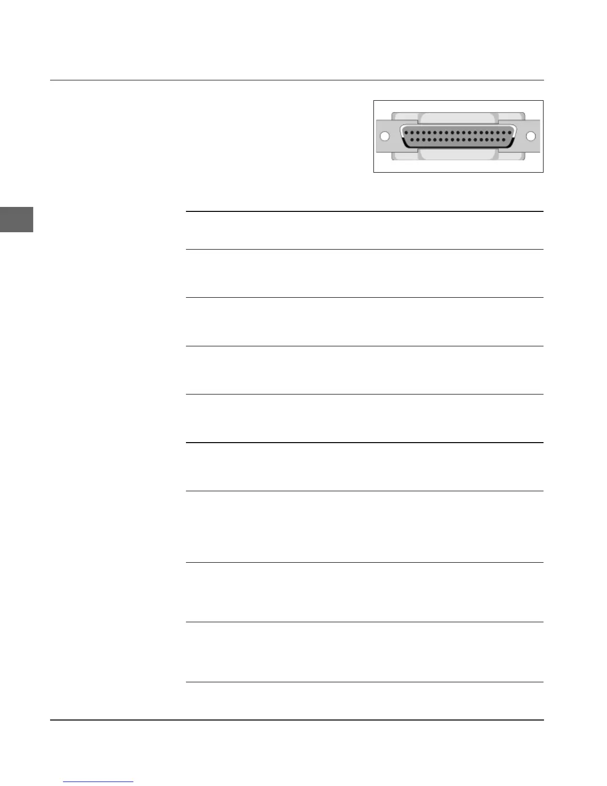
Pin assignment
Shielded twisted-pair data
transmission cable IBM Type 1.
UL- and CSA-certified. The
printer has a 37-pin DC-37S
connector.