D-13
Appendix D: Interface Data
* In the printer menu you can select Pin 3 and 21 (SSD), 7 and 25
(RS) or 12 and 30 (TR) as Busy line.
** Use the menu option DSR Signal to select whether the signal DM
is evaluated (option valid) or ignored (option invalid) by the
printer.
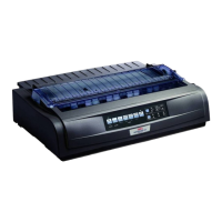
The signal levels described below are equivalent to the EIA-Stand-
ard RS-422A.
MARK Polarity: -0,2 to -6,0V: LOW = OFF = Logical "1"
SPACE Polarity: +0,2 to +6,0V: HIGH = ON = Logical "0"
Input Circuit equivalent to Am 26LS32
Schwellenpegel
Differenzeingang (V)
V
+ 200 mV
- 200 mV
Eingang
Eingang
Ausgang
+ 6 V
- 6 V
Maxi
Arbei
+
-
Maximum
Operating
Range
Signal levels
Circuits
Eingang
Ausgang +
Ausgang -
V
V
3,2 V
0,32 V
0 V
3,2 V
0,32 V
0 V
V
Ausgang -
Ausgang +
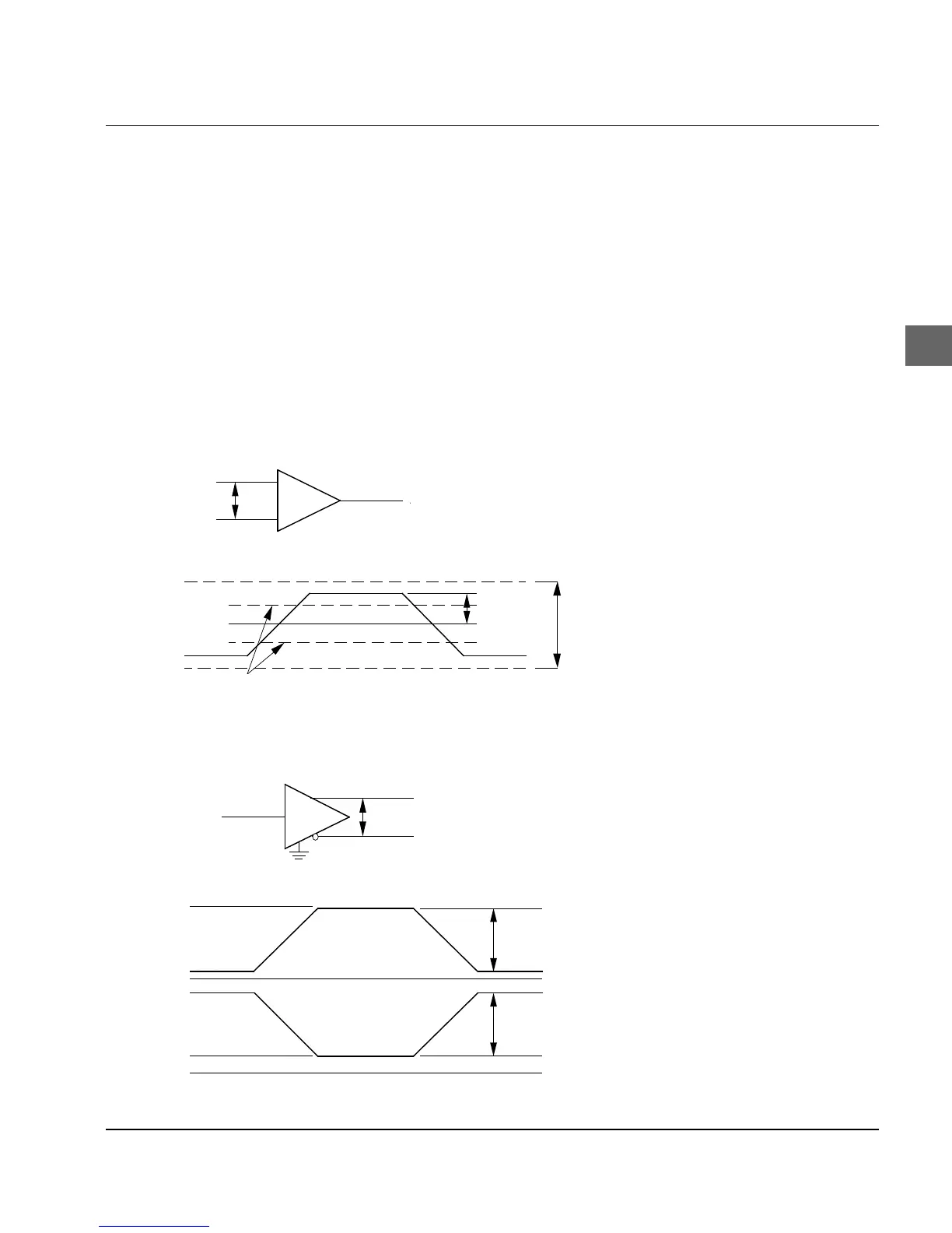
Output Circuit equivalent to Am 26LS31
DifferentiatingInput (V)
Input
Input
Output
Threshold Level
Input
Output -
Output +
Output +
Output -