D-6
Appendix D: Interface Data
*** You may set Pin 18 to
+5 V by selecting the menu
option Pin 18.
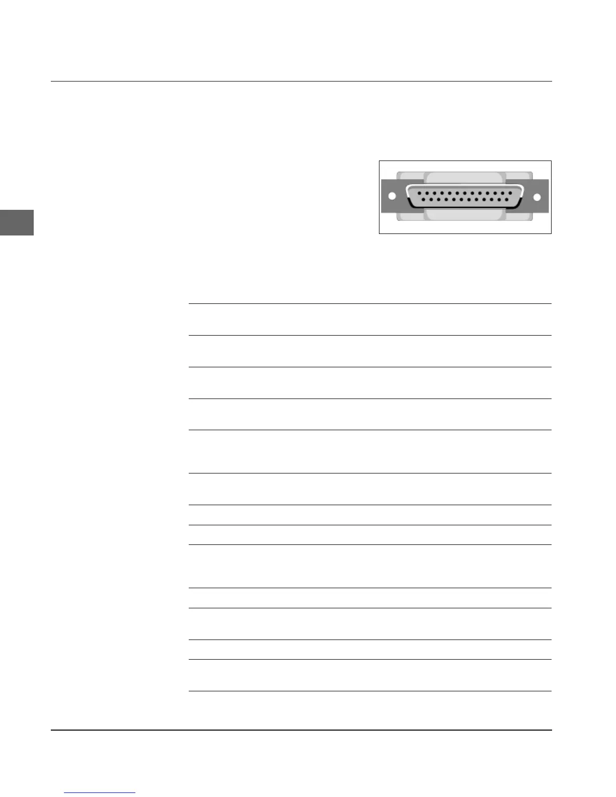
Technical specifications of a cable for a serial RS-232C-Interface:
25-pin plug: equivalent to DB25P
Plug housing: equivalent to DB-C2-J9.
Shielded Beldon cable or equiv-
alent with a maximum length of
15 m. The cable should be a
twisted-pair cable to prevent
signal interference and must be
UL- and CSA-certified. The
printer has a 25-pin DB-25S-plug.
Pin Signal Direction Description
1 Protective Ground, PG --- Connected to printer’s
casing.
2 Transmit Data, TD From printer Serial signal sent from the
printer.
3 Receive Data, RD To printer Serial signal received by
the printer.
4 * Ready to Send, RTS From printer Indicates that the printer
is ready to receive data.
5 Clear to Send, CTS To printer Indicates that system is
ready to send data to
printer.
6 ** Data Set Ready, DSR To printer Indicates that the
system is ready.
7 Signal Ground, SG --- Signal Ground.
8-10 Not assigned.
11 * Flow Control, SSD From printer Indicates that the printer
is not ready to receive
data.
12-17 Not assigned.
18 *** +5 V From printer Voltage of + 5 Volt
(max. 100 mA).
19 Not assigned.
20 * Data Terminal Ready, DTR From printer Indicates that printer is
ready to receive data.
21-25 Not assigned.
Pin assignment
* You can set Pin 4, 11 or 20
as flow control line by
selecting the menu option
Busy Line.
** You set the evaluation by
selecting the menu option
DSR Signal (Valid =
evaluate, Invalid = ignore).