D-8
Appendix D: Interface Data
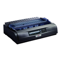
AT industry standard
9-pin to 25-pin
When using this circuit set
the menu option Busy Line
to DTR and Protocol to
READY/BUSY. If you select
the X-ON/X-OFF protocol,
the setting for Busy Line is
irrelevant. The value DSR of
the printer menu must be set
to Invalid.
Interface Wiring
To indicate that the printer is ready to receive data, select DTR,
SSD+, SSD- or RTS in the Busy Line menu.
Computer Drucker
Schutzerde 1 1 Schutzerde
TD 2 2 TD
RD 3 3 RD
RTS 4 4 RTS
CTS 5 5 CTS
DSR 6 6 DSR
DCD 8 8 DCD
DTR 20 20 DTR
Signalerde 7 7 Signalerde
Printer
Protective
Ground
Protective
Ground
Signal Ground
Signal Ground
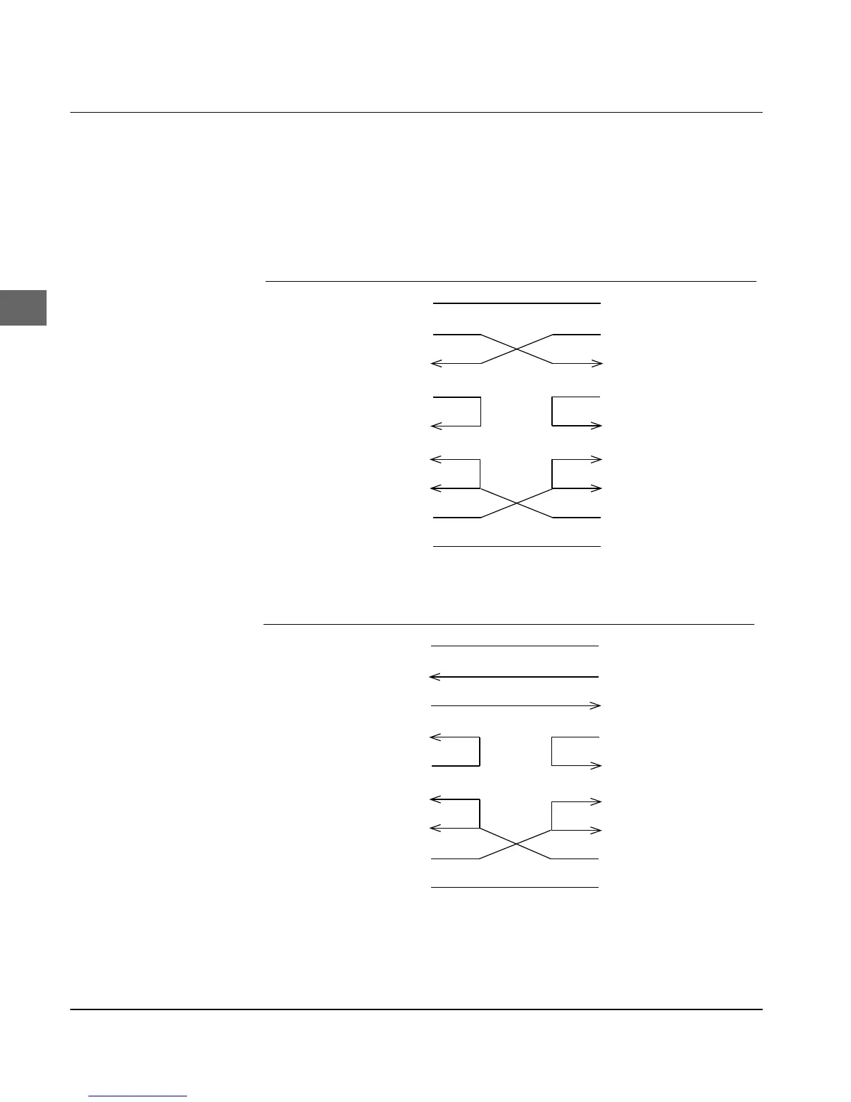
PC industry standard
25-pin to 25-pin
When using this circuit set
the menu option Busy Line
to DTR and Protocol to
READY/BUSY. If you select
the X-ON/X-OFF protocol,
the setting for Busy Line is
irrelevant. The value DSR in
the printer menu must be set
to Invalid.
Computer Drucker
Schutzerde 1 Schutzerde
RD 2 2 TD
TD 3 3 RD
CTS 8 4 RTS
RTS 7 5 CTS
DSR 6 6 DSR
DCD 1 8 DCD
DTR 4 20 DTR
Signalerde 5 7 Signalerde
Printer
Signal Ground
Signal Ground
Protective
Ground
Protective
Ground