22
VIEW
Status
Parameter
Error
Error log
Version
1 2
6. VIEW MENU
This menu is used possible to display a great deal of
information related to machine operation. Each label
brings together a set of information so that the user
can check the status of the unit and any current errors
or faults. The following keys are used to navigate this
menu:
T (
1
) Go back to the higher level menu
T (
2
) Go back to the main page (Home);
T To access a function, click on the text of that
function.
6.1. Navigating the menu
These pages display the status of the various components in the system. After accessing the "Status" func-
tion, you can browse the various pages using the buttons on the left and right sides of the window. The
following table shows the information available, and the possible statuses.
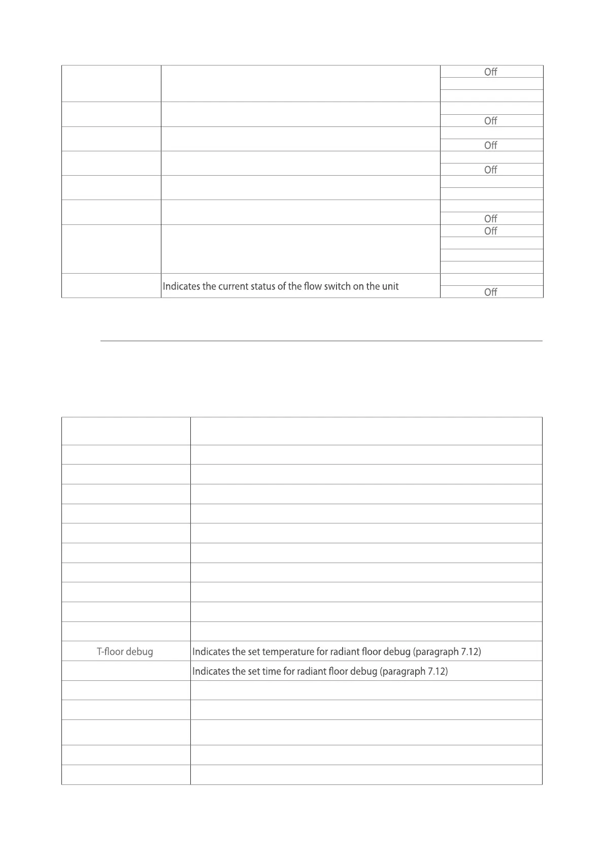
6.2. Viewing the status of the unit components (Status)
NB: all information contained in this menu is "read only".
Label Meaning Status
Compressor Indicates the current status of the compressor
On
O
Fan Indicates the current status of the fan
On
O
Unit status Indicates the status of the unit
Cool
Heat
Hot water
O
HP-pump Indicates the current status of the fan
On
O
Water tank Status of the electric heater in the DHW storage tank
On
O
3-way valve 1 Not used ---
3-way valve 2 Indicates the status of the 3-way valve on the system
On
O
Crankc. heater Indicates the status of the compressor casing heater
On
O
HP-heater 1
Indicates the status (for stage 1) of the optional electric heater, if
installed (paragraph 7.9)
On
O
HP-heater 2
Indicates the status (for stage 2) of the optional electric heater, if
installed (paragraph 7.9)
On
O
Chassis heater Indicates the status of the anti-freeze heater on the unit base
On
O
Plate heater
Indicates the status of the anti-freeze heater on the plate heat
exchanger of the unit
On
O
Defrost Indicates the current status of the defrosting cycle
On
O
Oil return Indicates the current status of the oil return cycle
On
O
23
Thermostat Indicates the current thermostat settings (paragraph 7.7) Cool
Heat
Other thermal Indicates the status of the additional heat source (paragraph 7.8)
On
2-way valve Indicates the status of the 2-way valve on the system
On
HP-Antifree Indicates the status of the anti-freeze protection
On
Gate-Ctrl Indicates the status of the external contact (paragraph 7.15)
Card in
Card out
4-way valve Indicates the status of the 4-way valve on the unit
On
Disinfection Indicates the current status of the anti-legionella cycle (paragraph 4.10)
Progess
Done
Error
Flow switch
On
These pages display the current values for the unit's operating parameters. After accessing the "Param-
eters" function, you can browse the various pages using the buttons on the left and right sides of the
window. The following table shows the information available.
6.3. Viewing the status of the unit parameters (Parameter)
NB: all information contained in this menu is "read only".
Label Meaning
T-outdoor Indicates the external air temperature detected by the unit
T-suction Indicates the temperature on the compressor inlet
T-discharge Indicates the compressor delivery temperature
T-Defrost Indicates the temperature for the defrosting cycle
T-water in PE Indicates the temperature of the water entering the plate heat exchanger
T-water out PE Indicates the temperature of the water leaving the plate heat exchanger
T-optional water sen. Indicates the temperature of the water leaving the optional heater (paragraph 7.9)
T-tank ctrl. Indicates the temperature detected in the water tank
T-economizer in Indicates the temperature on the economiser inlet
T-economizer out Indicates the temperature on the economiser outlet
Debug time
T-gas pipe Indicates the temperature detected on the gas side of the cooling circuit
T-liquid pipe Indicates the temperature detected on the liquid side of the cooling circuit
T-auto mode
Indicates the current set-point temperature, calculated using the climatic curve
(paragraph 4.7)
T-remote room Indicates the room temperature detected by the probe (paragraph 7.10)
Dis. pressure Indicates the compressor delivery pressure value