5
4. Push the print head in the direction of the arrow until
you hear a click, confirming that it has been inserted
properly, then close the print head compartment cover.
If, after installing the print head, the message “CHECK
PRINT HEAD” is displayed again, try to remove and
reinsert the print head pushing it harder. If the mes-
sage persists, remove the print head and clean the
electrical contacts of the print head and of the car-
riage, see “Cleaning the electrical contacts of the
print head”, under the “Maintenance” chapter.
To release the print head, push the levers in the di-
rection of the arrow.
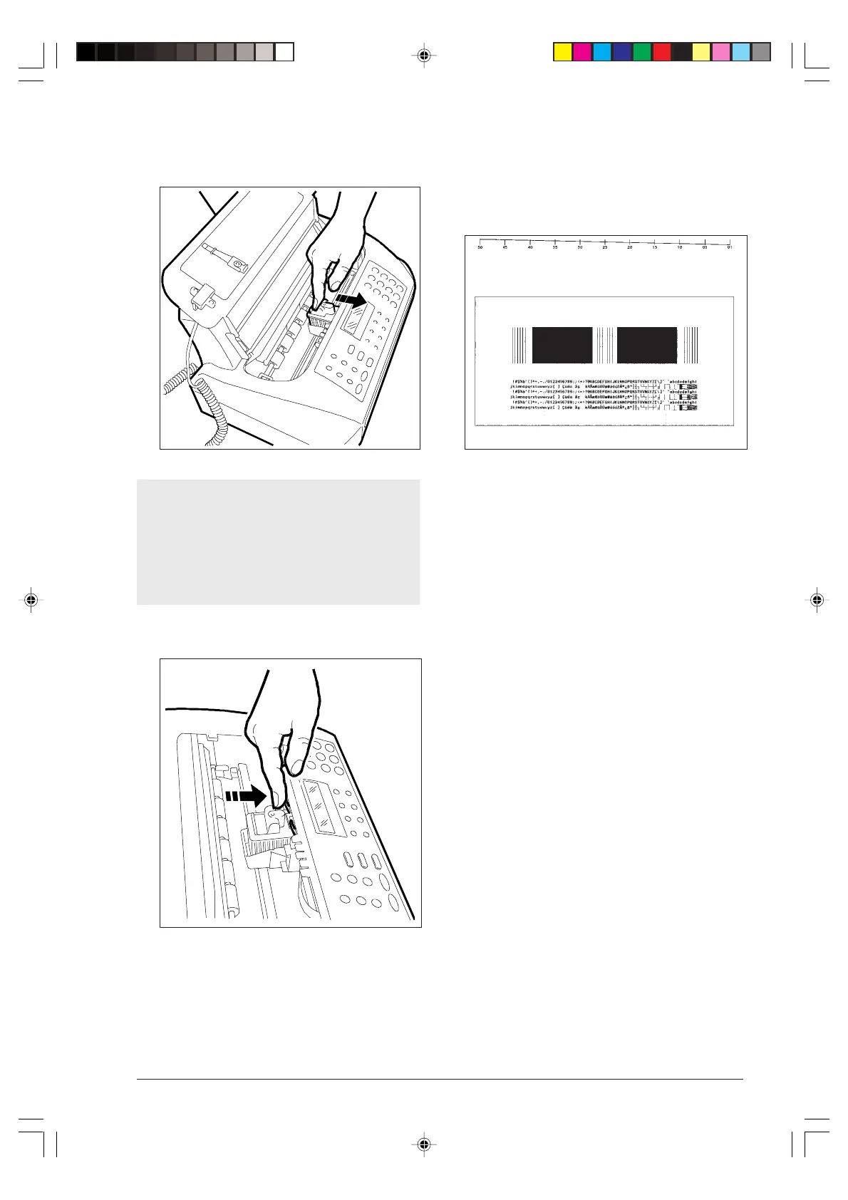
5. The fax machine automatically feeds a sheet of paper
and starts the nozzles cleaning and checking pro-
cedure, which ends with:
• printing, on the automatically fed sheet, the follow-
ing diagnostic result
containing:
-a numbered scale, to check ink flow and the elec-
trical circuits associated with the print head nozzles.
- a set of graphics and text, to assess print quality.
• displaying the message: “CHECK PRINT OUT,
1=EXIT 0=REPEAT”.
6. Examine the print sample as follows:
• Check the numbered scale for interruptions and
the black areas for horizontal white lines: if
none are present, then the print head is installed
properly and is operating normally. Set the value 1,
and the fax machine will go back to its initial waiting
mode and ready for use. The “AUTOMATIC RX”
message will be displayed on the upper line and
the “date and time” on the lower line.
• If, instead, you see interruptions or white lines,
set 0 to repeat only the nozzle cleaning operation:
if the new print sample continues to be unsatisfac-
tory, repeat the procedure again.
• If, after repeating the procedure three times, print
quality still fails to meet expectations, perform the
following operations consecutively, stopping as soon
as a satisfactory print sample is obtained:
- Use the fax machine to make a copy of a docu-
ment with the type of graphics or text you require
and assess its quality.
- Change paper type (the paper you are using may
be very porous) and repeat the procedure again.
- Remove and reinstall the print head.
- Remove the print head and visually check for the
presence of a particle on the print nozzle; if you
find one, carefully remove it, taking care not to
touch the electrical contacts; move the carriage
against the left side, then clean the print head pad,
numbered scale
black areas
ONE ORE MORE GAPS IN THE TOP NUMBERED SCALE AS WELL AS WHITE HORIZONTAL LINES
IN SOLID BLACK AREAS MEAN A LOWER PRINT QUALITY.
PLEASE, REFER TO THE CHAPTER 'MAINTENANCE' IN THE INSTRUCTIONS.
-1--1-10.p65 02/04/01, 9.175