XYAA6338 Service Manual 5-15
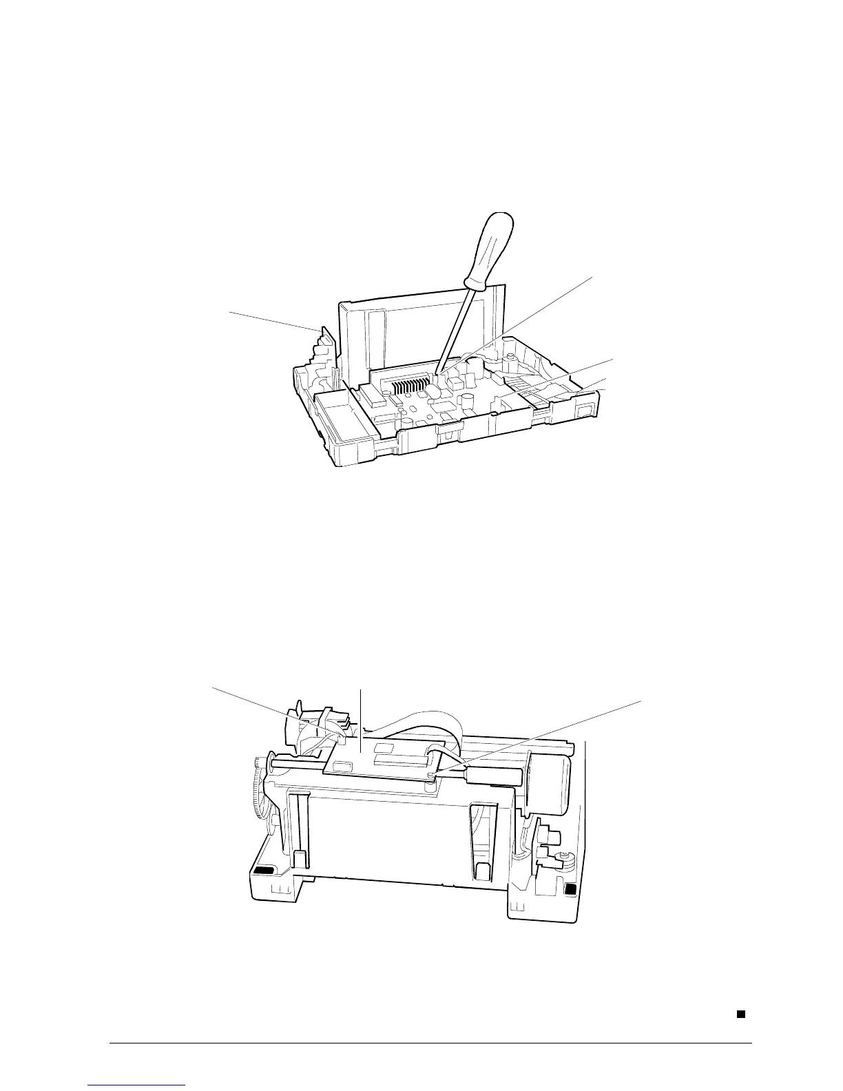
5.12 REMOVING THE BOARDS
5.12.1 Main Board
• Remove the case (Section 5.2).
• Lift the printer's mechanical assy.
• Disconnect all connectors.
• Remove screw A and then extract the main
board very carefully (Fig. 5-15).
Fig. 5-15
5.12.2 Drawer and Display Card
• Remove the case (Section 5.2).
• Lift the printer's mechanical assy.
• Disconnect the connector.
• Extract the main board very carefully (Fig. 5-15).
Drawer and
display card
Main board
5.12.3 Micr Board
• Remove the case (Section 5.2).
• Disconnect all connectors.
• Remove screws A and then remove the Micr
board.
Screw A
Micr Board
Fig. 5-16
A
A
.