6-2XYAA6338
Fig. 6-2
Fig. 6-3
Fig. 6-4
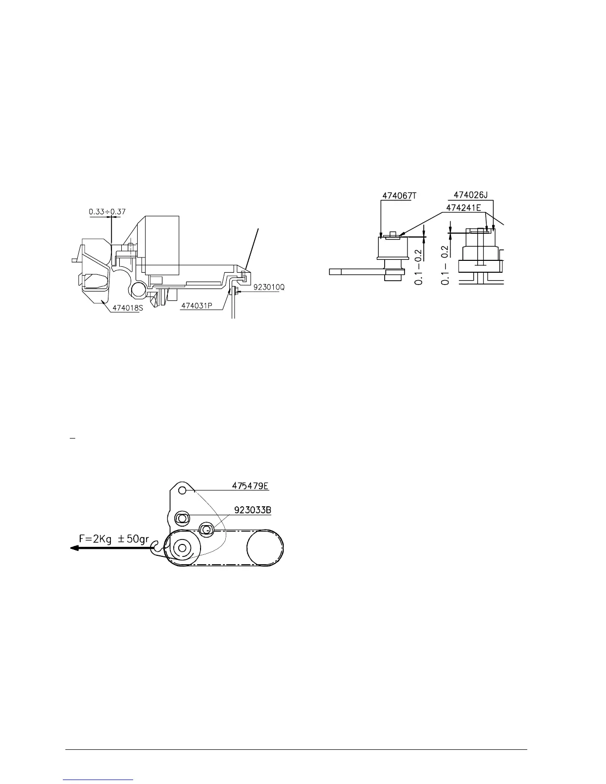
6.4 MOUNTING THE SNAP RINGS ON
THE CARRIAGE TRANSPORT
ASSEMBLY
During the assembly of codes 474067T, 474059B and
474026J, snap ring code 474241E must have a
clearance of 0.1 - 0.2 (Fig. 6-4). Clearance is obtained
by inserting a probe between the snap ring and the
stop point.
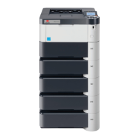
6.2 ADJUSTING THE PARALLELISM
AND PRINT HEAD-PLATEN
DISTANCE
By means of friction screws 923010Q, higher or lower
the plate code 474031P until obtaining the parallelism
between the print head and platen. Then check, using
a probe, for a clearance of 0.33 - 0.37 mm between
the needle profile and platen code 474018S (Fig 6-2).
Perform the adjustment procedure always maintaining
points A in contact with each other.
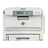
6.3 ADJUSTING THE TENSION OF THE
CARRIAGE TRANSPORT BELT
Pulling the end pulley support bracket with a
dynamometer in the direction of the arrow, tighten the
transport belt until reaching a value of 2 Kg
+ 50 gr. Using the screw code 923033B, block the
bracket code 475479E on the structure (Fig. 6-3).
A