DMTA-10043-01EN, Rev. C, July 2016
Instrument Description
17
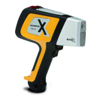
Figure 1‑1 The 27MG hardware components — Front and top views
1.4 Connectors
Figure 1-2 on page 17 illustrates the possible connections between the 27MG and
external devices.
Figure 1‑2 The 27MG connections
The universal serial bus (USB) and Transmit/Receive transducer connectors are
located on the top of the 27MG (see Figure 1-3 on page 18). The USB connector on the
27MG is only used for upgrading the internal operating software.
Strap ring
Display
Keypad
Transmit/Receive transducer
connectors
I/O door protecting
USB connector
Power key
Transmit/Receive
transducer
USB connector
(for software upgrades only)