DMTA-10043-01EN, Rev. C, July 2016
Chapter 9
60
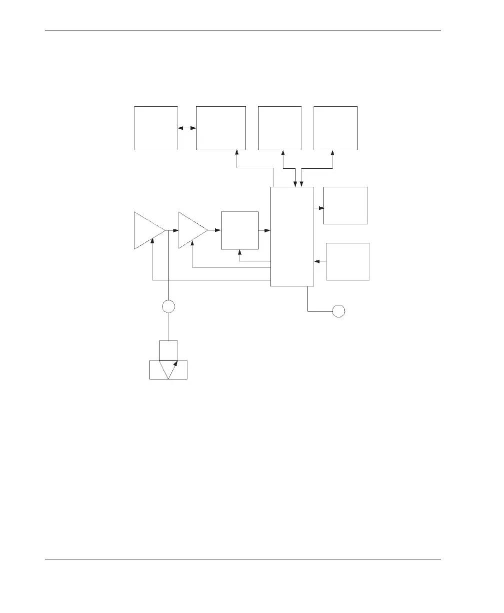
The microprocessor also directs the receiver/detector to identify the transducer type
using the I.D. pin of the transducer. Calibration values and gage setups are saved in
non-volatile RAM (random access memory). The keyboard informs the
microprocessor of user-entered changes of mode, values, and so on.
Figure 9‑1 27MG block diagram
Battery
Power
supply
ROM RAM
LCD
Keyboard
Pulser
AGC
amplifier
Detector
Control and
Measure
Transducer
USB
For software
upgrade only