15
Getting Started
3
3.4 CONNECTING SENSOR INPUTS
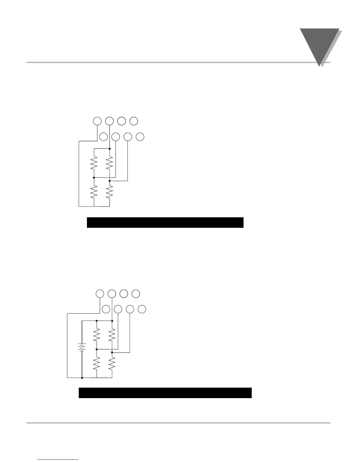
Figures 3-6 shows excitation supplied from the meter’s internal supply
(50 mA maximum) Select 5, 10, or 12 volt excitation at DIP switch.
Figure 3-6. Meter-powered Bridge Input
Figures 3-7 shows the connections required for an externally-powered bridge input: the
external supply is brought to the meter’s buffer circuits to permit ratiometric readings.
Set S1 DIP switch for external excitation for Figure 3-7 and 3-8.
Figure 3-7. Externally-powered Bridge Input
Connections with “typical wire colors”
+E = Positive Excitation (red)
-E = Negative Excitation (black)
+S = Positive Signal Input (green)
-S = Negative Signal Input (white)
Connections with “typical wire colors”
+E = Positive Excitation (red)
-E = Negative Excitation (black)
+S = Positive Signal Input (green)
-S = Negative Signal Input (white)

 Loading...


