23
Configuring The Meter
4
4.3.1 Scaling with Known Loads (On-Line Calibration)
For maximum resolution, find the maximum signal that will be applied to the
meter input.
• For regular voltage input, refer to the main body of Table 4-1.
• For millivolt or milliamp input, refer to the main body of Table 4-2.
Set the DIP switch positions as indicated at the top of either Table 4-1 or 4-2. The
numbers 1 through 8 in the top row of either table represent dip switches 1 through 8,
and the O, C or X directly below the number indicates the correct position of each switch.
• ‘O' Switch should be open or up.
• ‘C' Switch should be closed or down.
• ‘X' Switch is used to control excitation (refer to Table 2-3 to determine
correct position of these switches).
Once Dip switches have been positioned correctly, apply power. Proceed to the RD.CF
(Reading Configuration) and set R2 equal to the value in the right hand column of the
chart.
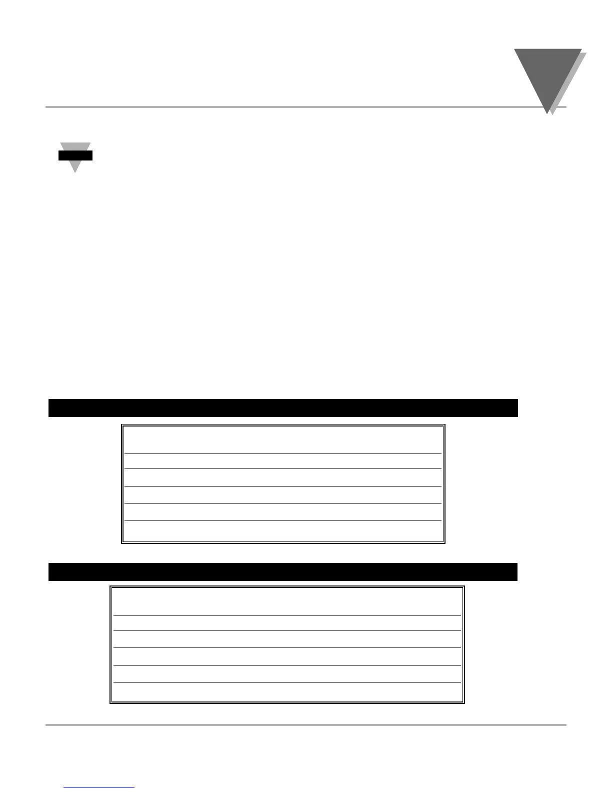
Table 4-1. Range Selection Dip Switch Positions For Regular Voltage Input
Table 4-2. Range Selection Dip Switch Positions For Millivolt/ Milliamp Input
Table 4-1. Range Selection Dip Switch Positions For Regular Voltage Input
Table 4-2. Range Selection Dip Switch Positions
For Millivolt and Milliamp Input
p
* Reading Configuration
12345678 12345678 12345678 RD.CF*
XOCOOXX0 XOCOCXX0 XOCCOXX0 R.2=
0 - 100 mV ±50 mV 0 - 20 mA 4
0 - 50 mV ±50 mV 0 - 10 mA 3
0 - 30 mV ±30 mV 0 - 6 mA 2
0 - 20 mV ±20 mV 0 - 4 mA 1
0 - 10 mV ±10 mV 0 - 2 mA 0
12345678 12345678 RD.CF*
XCOOOXXC XCOOCXXC R.2=
0 - 10 V ±5 V 4
0 - 5 V ±5 V 3
0 - 3 V ±3 V 2
0 - 2 V ±2 V 1
0 - 1 V ±1 V 0

 Loading...


