135
Appendix
the voltage tap can be used for measuring the power factor and capacitance of
C1 and C2 insulation of the bushing. In addition, this tap can be used for
monitoring the partial discharge during factory tests and insulation leakage
current (including partial discharge) during field service operation.
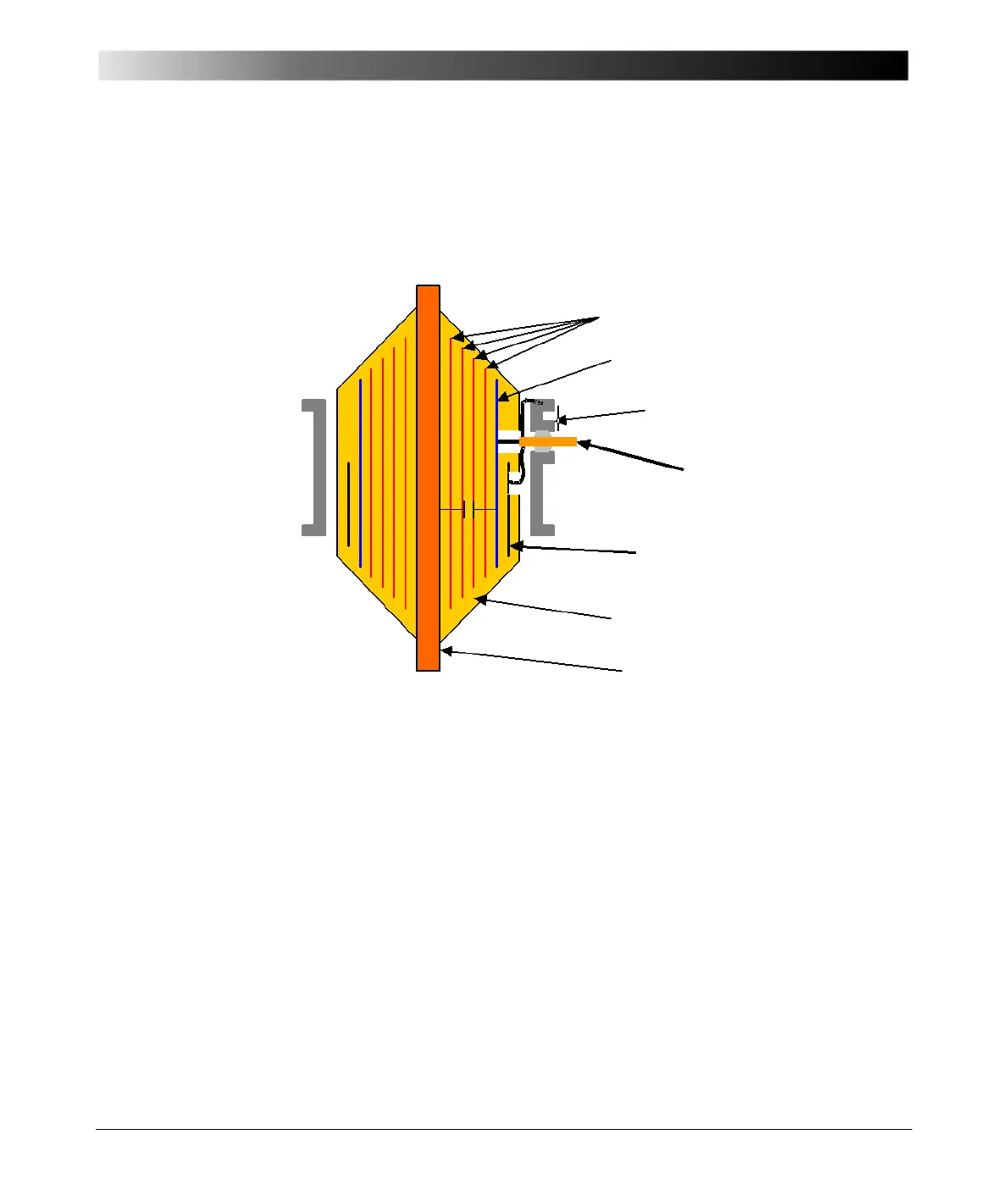
See Figure 12-2 for condenser design and voltage tap details.
Figure 12-2 Design/construction details of a typical condenser bushing
rated 115 kV and above
Condenser bushings rated 69 kV and below as per the IEEE Standards are
provided with C1 capacitance, which is the main capacitance. This capacitance
is formed by the oil/paper insulation between the central conductor and the C1
layer/foil, which is inserted during the condenser winding process. The C1 layer/
foil is internally connected to the test tap.
These bushings have an inherent C2 capacitance, which is formed by the
insulation between the C1 layer and the mounting flange. This insulation
consists of a few layers of paper with adhesive, an oil gap between the
condenser core and the mounting flange, and the tap insulator. Under normal
operating condition, the C1 layer/foil is automatically grounded to the mounting
flange with the help of the screw-in test tap cover that makes a connection
between the test tap spring and the flange. The C2 insulation under normal
operating condition is therefore shorted and not subjected to any voltage stress.
The test tap is used for measuring the power factor and capacitance of C1 and
Voltage Equalizers
C1 Layer/Foil
Mounting Flange
Voltage Tap Stud
C
2
Layer/Foil
(always grounded)
Oil Impregnated Paper
Central Conductor
C1
C2

 Loading...


