CP TD1 Reference Manual V 1.44
58
5.3 "UST" and "GST" Measurements Using the Guard
Technology
In electrical devices like power transformers there are a lot of insulation gaps,
which have to be checked separately:
• Winding to winding
• Winding to tank & core
• Bushings
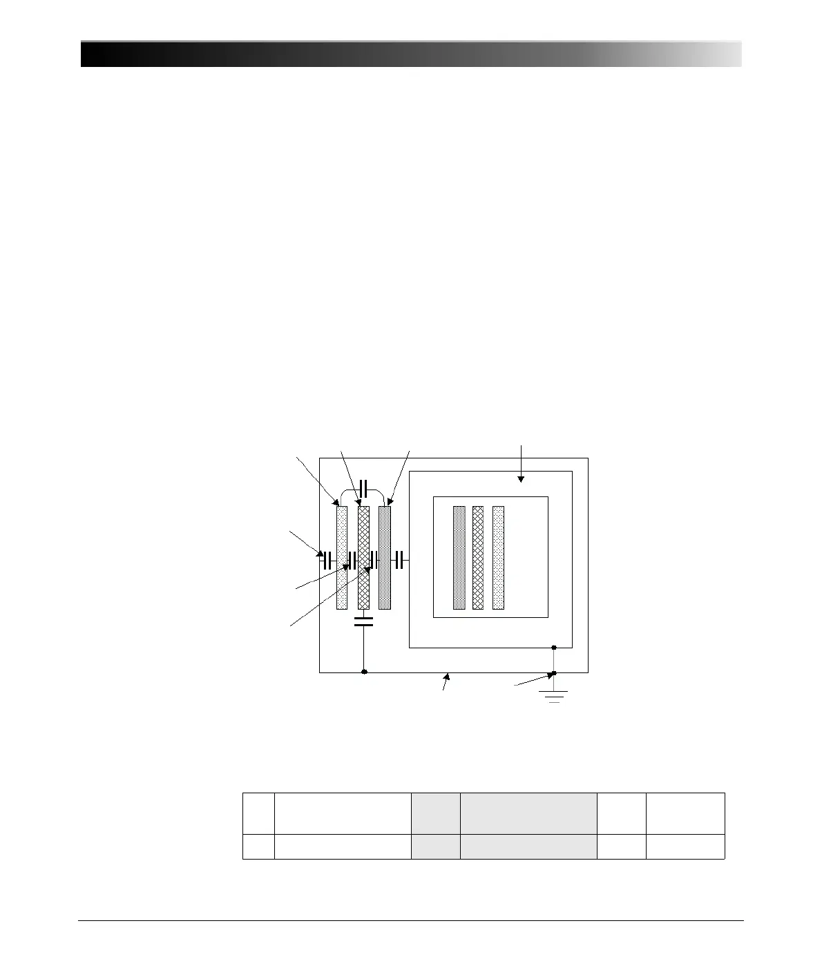
A three-winding transformer with the different insulation gaps is shown in figure
5-21. Only one phase is drawn. With a three-phase transformer the equivalent
circuit diagram is very similar, because normally the phases of the high-voltage
(H), the low-voltage (L) and the tertiary (T) windings are connected internally in
y or delta. This way only the sum of all three phases can be measured, the single
phases can not be measured separately.
Figure 5-21 Three-phase transformer with winding capacitances
H High-Voltage
winding
C H Cap. H to Ground C H-L Cap. H to
L
L Low-Voltage winding C L Cap. L to Ground C L-T Cap. L to T
CoreTL
H
C
H
C
H-L
C
L-T
C
H-T
C
T
C
L
Tank
G

 Loading...


