59
Capacitance and Dissipation Factor Measurement
For the separate measurement of all capacitors a so-called guard technique is
necessary. The single capacitors connected to guard are energized but not
measured.
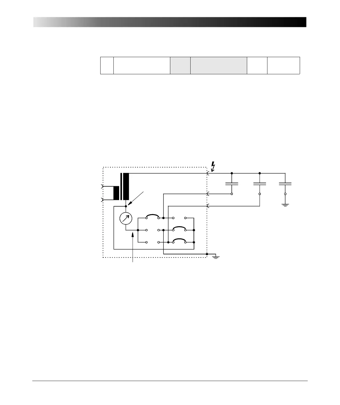
In Figure 5-22 a block diagram of the CP TD1 is shown with the guard
connection and measuring input. In the example case C
1
, C
2
and C
3
are
capacitors, connected to the CP TD1. C
1
is connected to input A, C
2
is
connected to input B and C
3
is connected to ground. All three capacitors are
energized. Only C
1
is measured, because the relay matrix only connects C
1
to
the measuring input (instrument), whereas the currents through C
2
and C
3
are
bypassed. C
2
and C
3
are connected to the foot-point of the HV transformer
(GUARD).
Figure 5-22 CP TD1 block diagram with GUARD and measuring input
To get more familiar with this technique we want to measure C HL, C HT and C
H of Figure 5-21. The high-voltage winding is connected to the test voltage
(high-voltage output of the CP TD1), the low-voltage winding is connected to IN
A and the tertiary winding is connected to IN B.
T Tertiary winding C T Cap. T to Ground C H-T Cap. H to
T
IN A
IN B
C
1
C
2
C
3
UST-A
C = C
1
Guard
Measuring input

 Loading...


