165
Appendix
The large difference of approximately 20% indicates a failure with 20% of the
turns. Due to the non-linear behavior, it can be assumed that the current, which
is flowing through the low-voltage winding is partly flowing through the magnetic
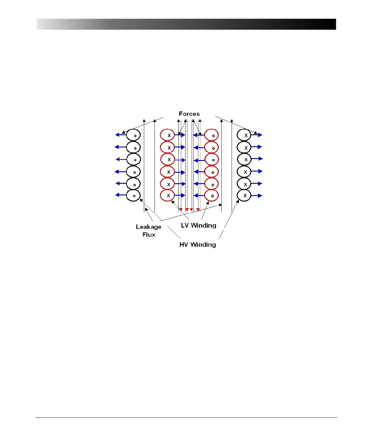
core. This can happen when the forces have significantly deformed the inner
turns (Figure 12-23).
Figure 12-23 Leakage flux and forces during a fault
The winding is probably interrupted and parts of the winding are contacting the
core which can be proven by measuring a resistance of 10m between LV
winding and core. For intact windings, this ratio is nearly totally independent
from the frequency in the discussed frequency range.
The ratio was measured with a test voltage of 200 V on the HV side. The
excitation current of the defective phase was approximately 340 mA whereas
the excitation current of the intact phases was approximately 10 mA.
12.9.11 Excitation Current
This test should be performed before any direct current (DC) tests. Results will
be incorrect because of the residual flux of the core, which was initiated by the
direct current.
By utilizing this test, short-circuited turns, poor electrical connections, core
lamination shorts, tap changer problems and other possible core and winding
problems can be detected. For a good interpretation of the results, comparison

 Loading...


