CP TD1 Reference Manual V 1.44
54
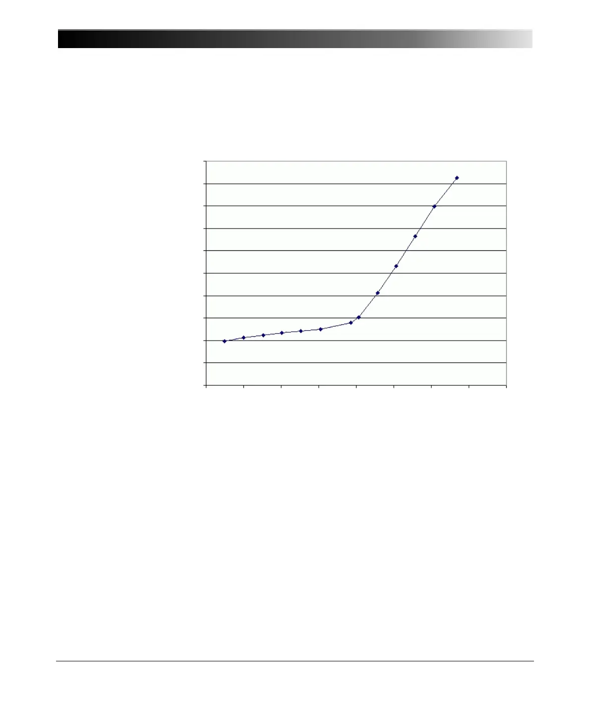
The dissipation factor is in many cases also dependent on the test voltage.
Figure 5-17 shows a measurement of a 6kV motor. Above 4kV, partial
discharges occur. This is the reason for the rise of DF.
Tan Delta Motor 6 kV
Figure 5-17 Voltage scan of a 6 kV motor
5.2 Measurement of Capacitance and Dissipation
Factor / Power Factor
Capacitance (C) and Dissipation Factor (DF) measurement was first published
by Schering in 1919 [2.1] and utilized for this purpose in 1924 (Figure 5-18). The
serial connected C
1
and R
1
represent the test object with losses, C
2
the loss-
1.6%
1.5%
1.4%
1.3%
1.2%
1.1%
1.0%
0.9%
0.8%
0.7%
0.6%
0V 1kV 2kV 3kV 4kV 5kV 6kV 7kV 8kV

 Loading...


