93
Capacitance and DF Measurement on High-Voltage Bushings
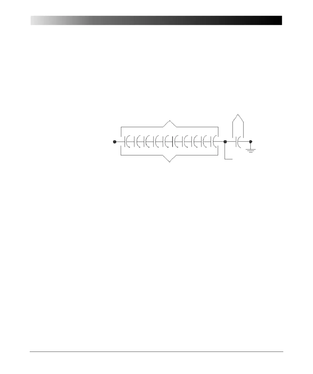
Notes:
– Equal capacitances, C
A
through C
J
, procedure equal distribution of voltage from the energized
center conductor to the grounded condenser layer and flange.
– The tap electrode is normally grounded in service except for certain designs and bushings used
with potential device.
– For bushings with potential taps, the C
2
capacitance is much greater than C
1
. For bushings with
power-factor tap, C
1
and C
2
capacitances may be same order of magnitude.
Figure 7-3 Condenser bushing circuit diagram [4.1]
Condenser bushings may have:
• "Resin-Bonded Paper insulation (RBP)
• "Resin-Impregnated Paper insulation (RIP)
• "Oil-Impregnated Paper insulation (OIP)
Composite
A bushing where the insulation consists of two or more coaxial layers consisting
of different insulating materials.
Compound-filled
A bushing where the space between the major insulation or conductor, if no
major insulation is used, and the inside surface of a protective weather casing
(usually porcelain) is filled with a compound that contains insulating properties.
Dry or unfilled
A bushing consisting of a porcelain tube with no filler in the space between the
shell and the conductor. These are usually rated 25 kilovolts and below.
C
A
=C
B
=C
C
=C
D
=C
E
=C
F
=C
G
=C
H
=C
I
=C
J
V
1
= V
2
= V
3
= V
4
= V
5
= V
6
= V
7
= V
8
= V
9
= V
10
C
1
C
2
C
K
Tap electrode
(normally grounded)
Grounded
layer/flange
Center
conductor
Line-to-ground system voltage
Main insulation
Tap insulation

 Loading...


