*1. The state may be Operation disabled when the command speed is less than the 1st Starting Frequency (F23)
or free-run state is set by FRS terminal or FsoE STO command input.
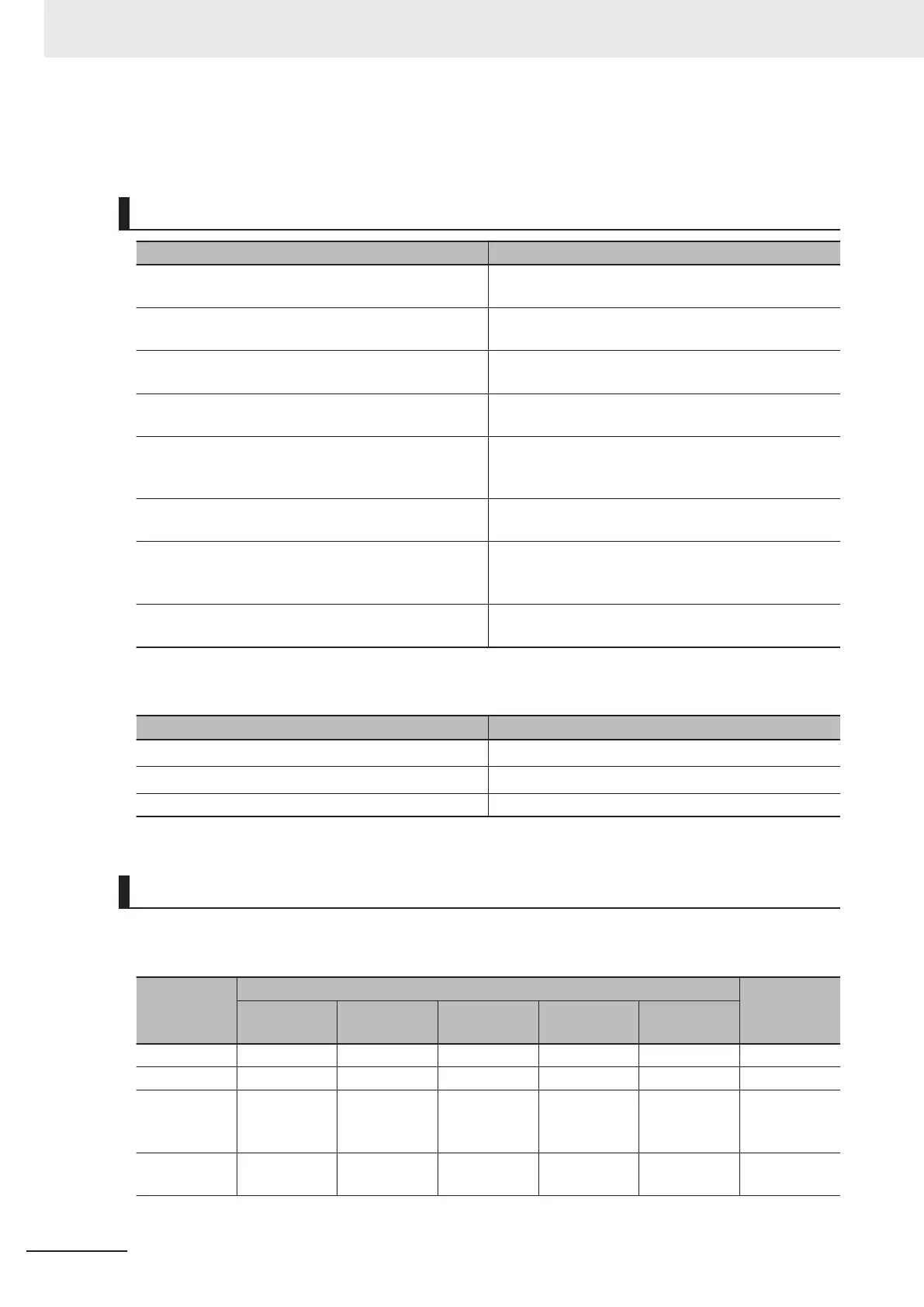
State Descriptions
State Description
Not ready to switch on The main power supply is turned ON and initialization
is in progress.
Switch on disabled Initialization is completed. Inverter parameters can be
set.
Ready to switch on The main circuit power supply can be turned ON.
Inverter parameters can be set.
Switched on The main circuit power supply is ON. (NUV ON)
Inverter parameters can be set.
Operation enabled Reference input is possible.
Inverter parameters can be set (only for parameters
that can be changed during operation).
Quick stop active The inverter is in a forced stop state.
Inverter parameters can be set.
Fault reaction active There was an error in the inverter and the cause deter-
mination is in progress.
Inverter parameters can be set.
Fault There was an error in the inverter.
Inverter parameters can be set.
If the state changes from “Operation enabled” to other states, the inverter decelerates and then stops.
The stop operation for each state is as shown below
.
State Stop operation
Switch on disabled, Ready to switch on
Set by Shut down option code (605B hex)
*1
Switched on
Set by Disable operation option code (605C hex)
*1
Fault reaction active, Fault Free run stop
*1. 2: Fixed to deceleration stop
State Control Commands
State is controlled by combining the bits in Controlword (6040 hex) as shown in the following table.
fr = fault reset, eo = enable operation, qs = quick stop, ev = enable voltage, so = switch on
Command
Controlword bit
Move to
Bit 7
fr
Bit 3
eo
Bit 2
qs
Bit 1
ev
Bit 0
so
Shutdown
Disabled Disabled
1 1 0 2, 6, 8
Switch on
Disabled
0 1 1 1 3
Switch on +
enable opera-
tion
Disabled
1 1 1 1
3 + 4
*1
Disable volt-
age
Disabled Disabled Disabled
0
Disabled
7, 9, 10
Appendices
A-4
M1 Series EtherCAT Type User’s Manual (I670)
 Loading...


