Index
(hex)
Sub-
index
(hex)
Pa-
rame-
ter No.
Function name Monitor or data range
Default
data
Set-
ting
dur-
ing
RUN
Unit
PDO
map
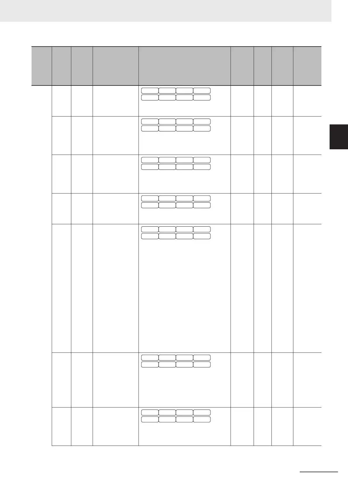
33 E50 1st Frequency
Conversion Coef-
ficient
V/f DTV
PG V/f PG DTV
SLV PGV
PM SLV PM PGV
0.01 to 600.00
30
√
--- Possible
34 E51 Display Coeffi-
cient for Integrat-
ed Power
V/f DTV
PG V/f PG DTV
SLV PGV
PM SLV PM PGV
0.000: Cancel/reset
0.001 to 9,999
0.01
√
--- Possible
38 E55 2nd Overload
Warning Detec-
tion Level
V/f DTV
PG V/f PG DTV
SLV PGV
PM SLV PM PGV
0.00: Disable
0.01 to 176.0
21
√
A Possible
39 E56 2nd Overload
Early W
arning
Detection T
imer
V/f DTV
PG V/f PG DTV
SLV PGV
PM SLV PM PGV
0.01 to 600.00
10
√
s Possible
3E E61 Input Terminal
[AI1] Function
Selection
V/f DTV
PG V/f PG DTV
SLV PGV
PM SLV PM PGV
0: Frequency command
1: Auxiliary frequency setting 1
2: Auxiliary frequency setting 2
3: PID command
5: PID feedback
6: Ratio setting
7: Analog torque limiter
9: Torque bias
10: T
orque command
11: Torque current command
17: Speed limit for forward rotation
18: Speed limit for reverse rotation
20: Analog signal input monitor
21: PID feed forward
0 --- --- Possible
42 E65 Reference Loss
Detection Opera-
tion Selection
V/f DTV
PG V/f PG DTV
SLV PGV
PM SLV PM PGV
0: Deceleration stop
20 to 120: Continuous operation fre-
quency ratio
999: Disable
*1
999
√
% Possible
4D E76 Main Circuit DC
Voltage Low-volt-
age Detection
Level
V/f DTV
PG V/f PG DTV
SLV PGV
PM SLV PM PGV
200 to 400 (200 V class series)
400 to 800 (400 V class series)
235
√
V Possible
Appendices
A-117
M1 Series EtherCAT Type User’s Manual (I670)
A-4 Lists of Manufacturer Specific Objects 2
(Inverter Parameters)
A
A-4-6 E Group Parameter List (Terminal Functions)
 Loading...


