(All bits are ON or active with 1.)
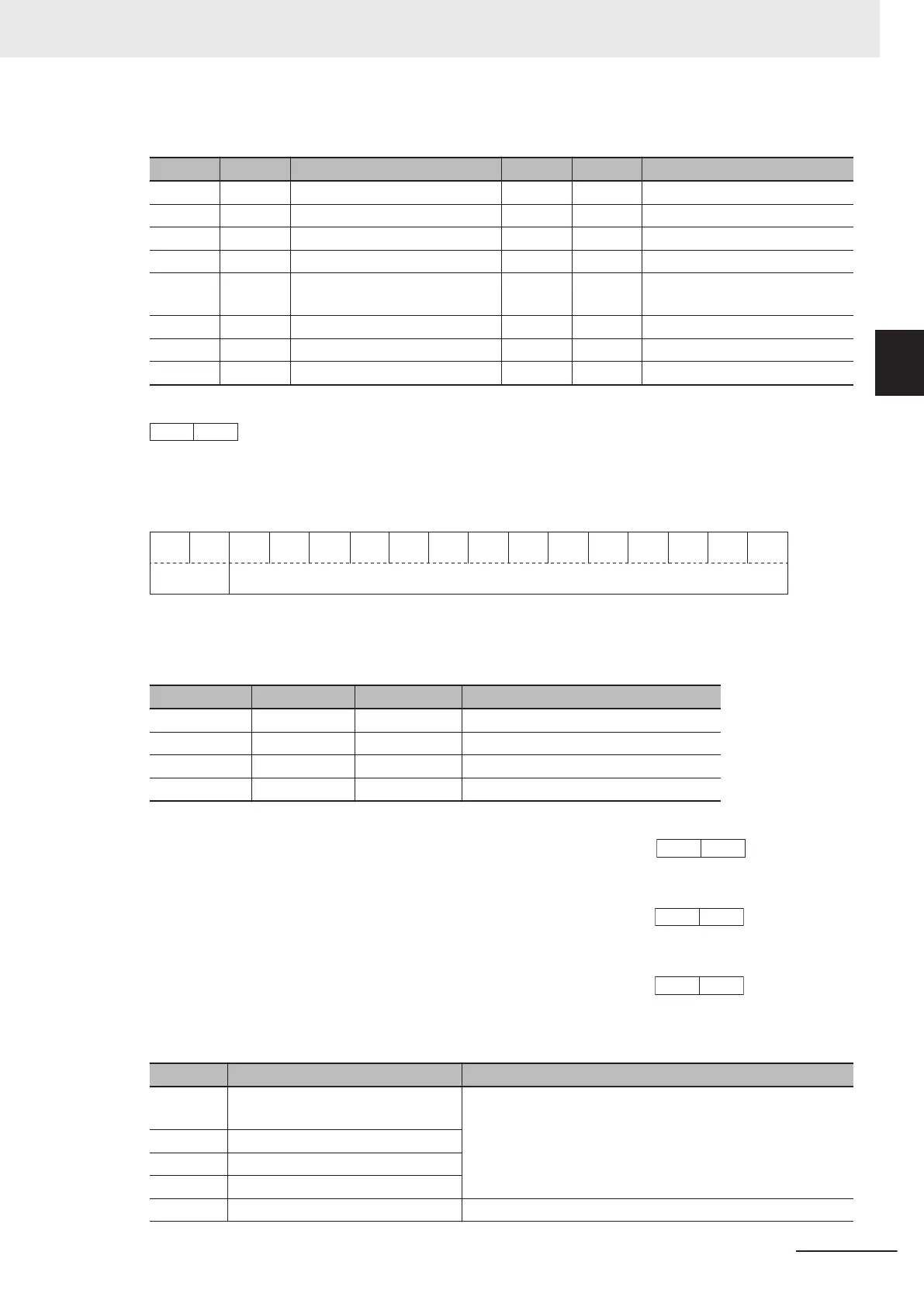
Bit Symbol Description Bit Symbol Description
0 FAR1 Constant speed arrival 8 TRY During retry
1 FDT1 Over set Frequency arrival 9 OHF Fin Overheat warning
2 IRDY Operation ready 10 LIFE Life warning
3 SETM 2nd motor selection 11 OLP During active drive
4 IPF During restart after instantane-
ous power failure
12 OL2 Overload warning 2
5 THM Thermal warning 13 LOC Light load detection
6 REF RUN command source 14 OL Overload warning
7 FAN Fan operation signal 15 0 ---
Example: Running Status 3 Monitor (3003-47 hex) = 0281 hex
→ 0000 0010 1000 0001
b
= FAR1, F
AN, and OHF are ON
Data Format [45]: Floating Point Data
15 14 13 12 11 10 9 8 7 6 5 4 3 2 1 0
Exponent
part
Mantissa part
Exponent part: 0 to 3, Mantissa part: 0 to 9,999
Value represented in this format = Mantissa part × 10 to the power of (exponent part - 3)
Value Mantissa part Exponent part 10 to the power of (exponent part - 3)
0.000 to 9.999 0 to 9,999 0 0.001
10.00 to 99.99 1,000 to 9,999 1 0.01
100.0 to 999.9 1,000 to 9,999 2 0.1
1,000 to 9,999 1,000 to 9,999 3 1
Example: Data Used Integrating Electric Power (3010-53 hex) = 9,999 kW
9,999 = Mantissa part: 9,999 (270F hex), Exponent part: 2 = A70F hex →
Example: Data Used Integrating Electric Power (3010-53 hex) = 999.9 kW
999.9 = Mantissa part: 9,999 (270F hex), Exponent part: 1 = 670F hex →
Example: Data Used Integrating Electric Power (3010-53 hex) = 99.99 kW
99.99 = Mantissa part: 9,999 (270F hex), Exponent part: 0 = 270F hex →
Data Format [67]: RUN Command Source Monitor
Code Description Remarks
0 Digital Operator positive direction
terminal
Same as the selection for RUN Command Selection
(3004-03 hex/301F-03 hex)
1 Terminal command (FW or RV)
2 Digital Operator forward rotation
3 Digital Operator reverse rotation
4 to 20 Reserved
Appendices
A-181
M1 Series EtherCAT Type User’s Manual (I670)
A-4 Lists of Manufacturer Specific Objects 2
(Inverter Parameters)
A
A-4-17 Communication Data Formats of Parameters
 Loading...


