Item Description
Minimum unit of operation
time
0: 0.01
1: 0.1
2: 1
3: 10
Data part of operation time Exponent part 0: 000 to 999
Exponent part not 0: 100 to 999
Example: Pattern Operation Stage 1 Operation Setting (3006-17 hex) = Reverse, 2nd Acceleration/
Deceleration Time, and 10.0 s
Rotation direction: Reverse (8000 hex)
Acceleration/Deceleration time: 2nd Acceleration/Deceleration T
ime (1000 hex)
Operation time: 10.0 s = 0.1 × 100 (0400 hex + 0064 hex)
Therefore, the set value is
8000 hex + 1000 hex + 0400 hex + 0064 hex = 9464 hex →
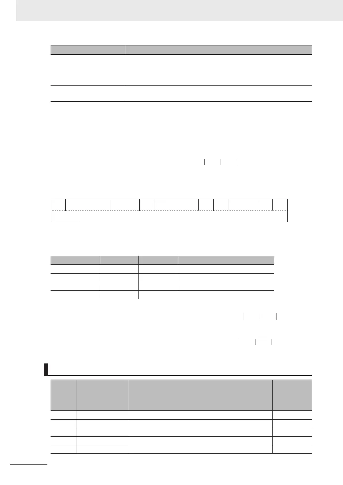
Data Format [93]: Floating Point Data
15 14 13 12 11 10 9 8 7 6 5 4 3 2 1 0
Exponent
part
Mantissa part
Exponent part: 0 to 3, Mantissa part: 0 to 9,999
Value represented in this format = Mantissa part × 10 to the power of (exponent part - 1)
Value Mantissa part Exponent part 10 to the power of (exponent part - 1)
0.0 to 999.9 0 to 9,999 0 0.1
1,000 to 9,999 1,000 to 9,999 1 1
10,000 to 99,990 1,000 to 9,999 2 10
100,000 to 999,900 1,000 to 9,999 3 100
Example: Integrated Power Monitor (3010-52 hex) = 12,340
12,340 = Mantissa part: 1,234 (04D2 hex), Exponent part: 2 = C4D2 hex →
Example: Integrated Power Monitor (3010-52 hex) = 567.8
567.8 = Mantissa part: 5,678 (162E hex), Exponent part: 0 = 162E hex →
Data Format of Inverter Parameters
Parame-
ter No.
EtherCAT Object Parameter
Communica-
tion data for-
mat
(2 bytes)
F00 3004-01 hex Operator Operation Prevention Function Selection 1
F01 3004-02 hex 1st Frequency Reference Selection 1
F02 3004-03 hex 1st RUN Command Selection 1
F03 3004-04 hex 1st Maximum Output Frequency 3
F04 3004-05 hex 1st Base Frequency 3
Appendices
A-184
M1 Series EtherCAT Type User’s Manual (I670)
 Loading...


