2 Nomenclature and Installation
2 - 6
CJ-series EtherCAT Slave Units Operation Manual (W541)
This section describes the functions of the rotary hardware switches on the front panel of the EtherCAT
Slave Unit.
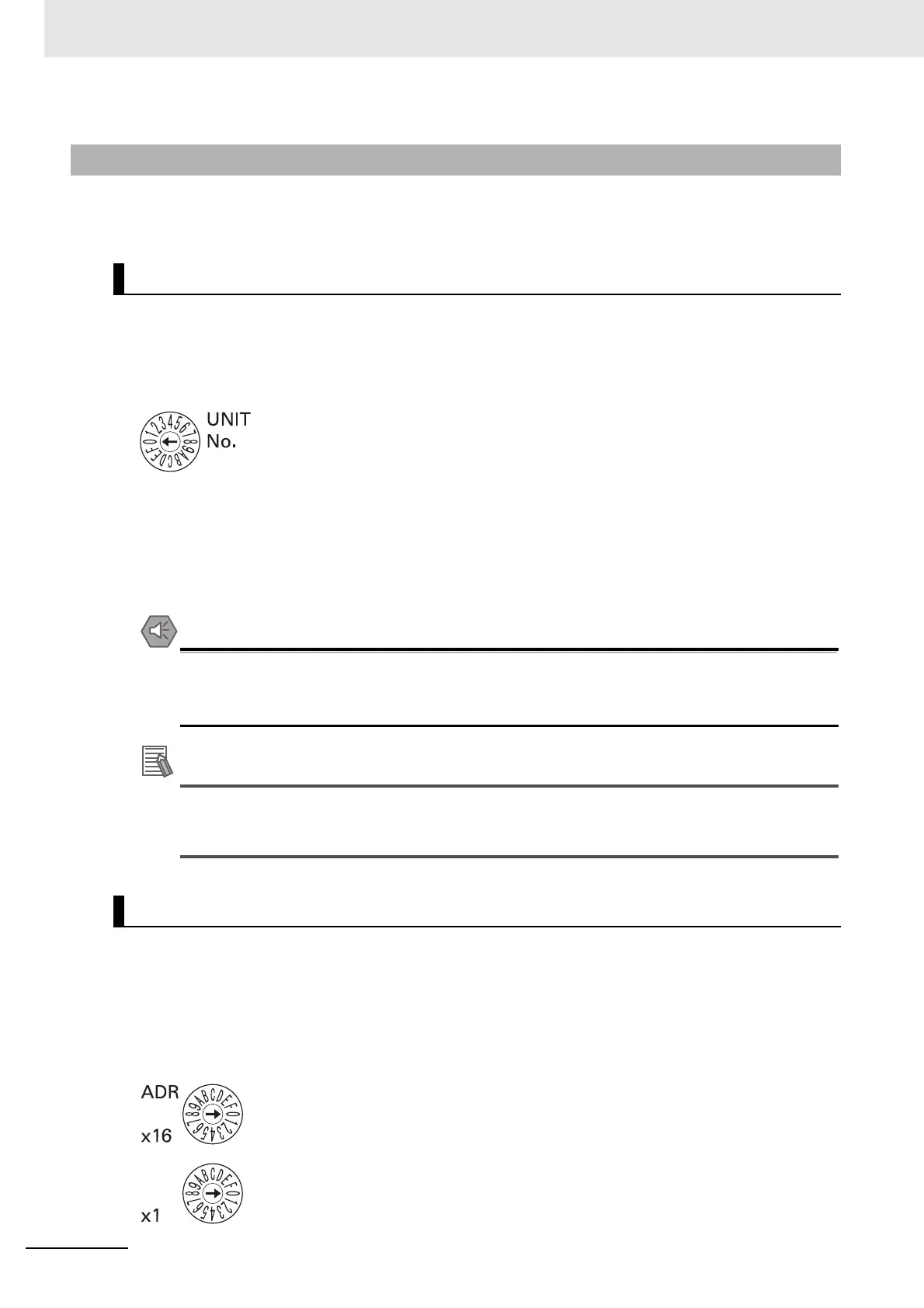
The unit number switch sets the unit number of the EtherCAT Slave Unit as a CPU Bus Unit. The unit
number determines which data area words and DM area words are allocated to the Unit that contain
data such as unit status, slave status, the I/O Communication Area Setting Table and the I/O Commu-
nication Area Reference Table.
Setting method: One-digit hexadecimal
Setting range: 0 to F hex
The unit number is set to 0 at the factory.
You can set any unit number from 0 to F as long as it has not been set on another CPU Bus Unit con-
nected to the same CPU Unit.
• Use a small flat-blade screwdriver to turn the rotary switches; be careful not to damage the
switch.
• Always turn OFF the PLC’s power supply before setting the unit number.
If the same unit number is set on more than one CPU Bus Unit mounted in a PLC, a Unit Num-
ber Duplication error will occur in the PLC and the EtherCAT Slave Unit will not be able to start
operating.
The node address switches set the node address of the EtherCAT Slave Unit to enable the EtherCAT
master to recognize the EtherCAT Slave Unit.
The value of node address is loaded to register 0012h of the EtherCAT slave controller when the power
supply to the CJ1W-ECT21 is turned ON.
The upper switch sets the sixteens digit (most significant digit) and the lower switch sets the ones digit
(least significant digit).
2-1-3 Switch Settings
Unit Number Switch
Node Address Switches