80
2-1 Nomenclature
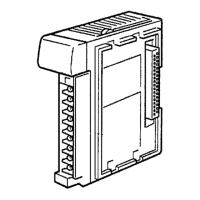
2-1-1 Analog Input Unit
Indicators
Input terminal 1
Input terminal 2
Input terminal 3
Input terminal 4
Protective
ground terminal
Power supply
cable
DIP switch
Left View
Front View
CQM1-AD041
Terminal screws: M3
Name Color Function
RDY Green Lit while the CQM1H/CQM1 is turned on and the
Analog Input Unit is operating normally.
ERR Red Lit when pins 1 to 8 of the DIP switch on the left side
of the Analog Input Unit are all set to OFF (i.e.,
when the conversion of all inputs is prohibited).
BROKEN WIRE Red Lit when an broken input wire is detected in an input
range of 4 to 20 mA at 1 to 5 V.
2CH/4CH Orange Lit when there are four words occupied. Not lit when
there are two words occupied.
Terminal Usage
Input terminal 1 Connect analog input for input 1.
Input terminal 2 Connect analog input for input 2.
Input terminal 3 Connect analog input for input 3.
Input terminal 4 Connect analog input for input 4.
Protective ground terminal Connect the shielded wire of the analog input cable.
Indicators
Terminals
Nomenclature Section 2-1
 Loading...


