!
82
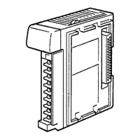
2-1-2 Analog Power Supply Unit
Indicators
Connector for the power supply
cable of the Analog Input Unit
CQM1-IPS01
Indicators
Connectors for the power supply
cable of the Analog Input Unit
Connector 1 Connector 2
CQM1-IPS02
Name
Color Function
P/S (incorporated by
the CQM1-IPS01
only)
Green Lit when power is supplied to the Analog Input
Unit via the CQM1-IPS01.
P/S1 (incorporated by
the CQM1-IPS02
only)
Green Lit when power is supplied to the Analog Input
Unit via Connector 1 of the CQM1-IPS02.
P/S2 (incorporated by
the CQM1-IPS02
only)
Green Lit when power is supplied to the Analog Input
Unit via Connector 2 of the CQM1-IPS02.
Note The P/S, P/S1, and P/S2 indicators are not lit when the power supply cable is
disconnected.
Cable Connections
• Connect the power supply cable of the Analog Input Unit to the power supply
connector of the Analog Power Supply Unit and secure the power supply cable
connector with screws.
• The CQM1-IPS02 incorporates two power supply connectors. The power sup-
ply cable of the Analog Input Unit can be connected to either one of the power
supply connectors.
Caution Be sure to turn off the Analog Power Supply Unit before connecting or discon-
necting the power supply cable of the Analog Input Unit. After connecting the
power supply cable, secure the power supply cable with the lock screws.
Indicators
Nomenclature Section 2-1
 Loading...


