134
Note When the mode selector is set to SET, the operation indicator and stability op-
eration indicator are used to monitor teaching. Refer to 4-1-1 E3X-MA11 Optical
Fiber Photoelectric Module for details.
Cable length switches
(Refer to 2-2-2 E2C-MA11
Proximity Sensor Module
for details.)
Timer selector
0 ms: No timer
10 ms: OFF-delay timer
(Refer to 2-2-2 E2C-MA11
Proximity Sensor Module
for details.)
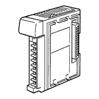
Side View
2-2 Switch Settings
2-2-1 E3X-MA11 Optical Fiber Photoelectric Module
E3C-MA11 Photoelectric Module
Setting Function
Light⋅ on The control output is ON when there is light incident.
Dark⋅ on The control output is ON when there is no light incident.
Setting Function
0 ms No timer
10 ms 10-ms OFF delay timer active
Timing Charts
Timer selector set to OFF (0ms) Timer selector set to ON (10 ms)
Operation indicator
(orange)
ON
OFF
Control output
ON
OFF
Light received
Light not received
Operation mode selector set to L S on (Light
ON)
10 ms
Operation mode selector set to L S on (Light
ON)
Operation indicator
(orange)
ON
OFF
Control output
ON
OFF
Light received
Light not received
Operation mode selector set to D S on (Dark
ON)
Operation indicator
(orange)
ON
OFF
Control output
ON
OFF
Light received
Light not received
Operation mode selector set to D S on (Dark
ON)
10 ms
Operation indicator
(orange)
ON
OFF
Control output
ON
OFF
Light received
Light not received
Note The operation mode selector and timer selector must be set before mounting the
E3X-MA11 to the Sensor Unit.
Setting Function
RUN Normal operation
SET Axis adjustment or sensitivity adjustment (teaching).
Operation Mode Selector
Timer Selector
Mode Selector
Switch Settings
Section 2-2
 Loading...


