36
CQM1-G7M01 Output Master
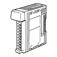
Front View
Terminal screws: M3
(Optimum tightening torque: 0.5 N S m)
Indicators (see following table)
+
–
+
–
Transmission terminal 1 (see page 40)
For connection of transmission cable from
Master or Expansion Master.
Transmission terminal 2 (see page 40)
For connection of transmission cable to next
Expansion Master or Slave.
Name Color Function
RDY Unit Ready Green Lit when power is on and if
CQM1H/CQM1 recognizes a Master.
OUT 1CH OUT Mode Orange Lit while number of outputs set to 1
word (16 points). Not lit when set to 2
words (32 points).
ADR No.2 Unit 2 Orange Lit when Unit 2 set. Not lit when Unit 1
set.
T/R Transmitting Red Flashes during transmission with
power turned on. Lit when there is a
transmission error. Not lit when there
is an error in the Expansion Master.
Note The positive and negative terminals of the transmission terminals 1 and 2 are
shorted internally.
Transmission terminals 1 and 2 can be connected in any order.
2-2 Switch Settings
Remove the terminal block to expose the DIP switch underneath. Refer to the
CQM1H Operation Manual (W363) or the CQM1 Operation Manual (W226) for
the method of removing the terminal block.
Use a thin-tipped object, such as a small screwdriver, to set the switches.
DIP switch
Indicators
Switch Settings
Section 2-2
 Loading...


