103
DST1-MRD08SL-1 Section 5-3
7 to 10
13 to 16
T0 to T3 Terminals for test outputs
21, 22 V1 Power terminals for driving internal relays. (24 VDC)
31, 32 G1
23 to 30
33 to 40
OUT0 to OUT3
C0 to C3
OUT0e to OUT3e
C0e to C3e
Terminals for safety outputs
Outputs of terminals 23/33 (OUT0) and 24/34 (OUT0e) are the same.
Output of terminals 25/35 (OUT1) and 26/36 (OUT1e) are the same.
Output of terminals 27/37 (OUT2) and 28/38 (OUT2e) are the same.
Output of terminals 29/39 (OUT3) and 30/40 (OUT3e) are the same.
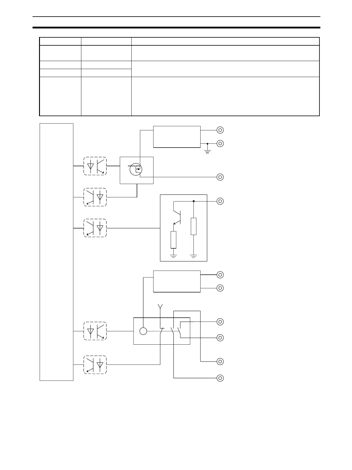
Terminals Names Functions
I/O Power Supply
Circuit
Internal
Circuit
Test Output Circuit
V0
V0+
G0
T0...T3
Safety Input Circuit
IN0...IN3
I/O Power Supply
Circuit
Safety Output Circuit
V1
V1+
G1
OUT0
...OUT3
X
C0...C3
OUT0e
...OUT3e
C0e...C3e
V0+

 Loading...


