5
Standard Models Section 1-2
1-2 Standard Models
As shown in the following tables, the DST1 Series consists of Input Terminals,
I/O Terminals, and Logic Terminals.
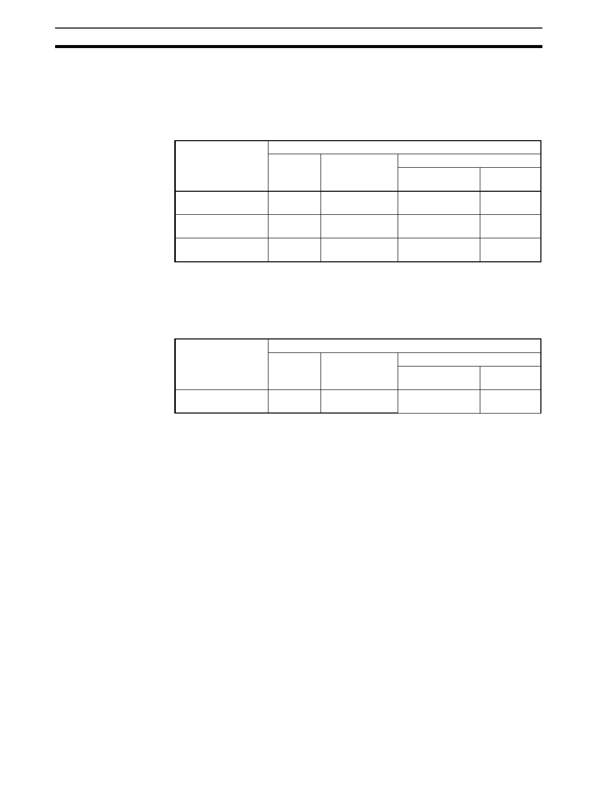
1-2-1 Input Terminals and I/O Terminals
Note Each test output can be set to function as a test output or a standard output.
Test outputs are used in combination with a safety input. Broken wires in an
external indicator can be detected for terminal T3 only.
1-2-2 Logic Terminals
Note (1) Each test output can be set to function as a test output or a standard out-
put. Test outputs are used in combination with a safety input. Broken
wires in an external indicator can be detected for terminal T3 only.
(2) Use Network Configurator version 2.0 or higher to set the DST1-
XD0808SL-1.
Model I/O capacity
Safety
inputs
Test outputs Safety outputs
Semiconductor
outputs
Relay
outputs
DST1-ID12SL-1 12 inputs 4 outputs
(See note.)
--
DST1-MD16SL-1 8 inputs 4 outputs
(See note.)
8 outputs -
DST1-MRD08SL-1 4 inputs 4 outputs
(See note.)
- 4 outputs
Model I/O capacity
Safety
inputs
Test outputs Safety outputs
Semiconductor
outputs
Relay
outputs
DST1-XD0808SL-1 8 inputs 4 outputs
(See note 1.)
8 outputs -

 Loading...


