133
Logic Terminal Wiring Examples Section 8-3
8-3 Logic Terminal Wiring Examples
8-3-1 Stopping Outputs by Using an Emergency Stop Switch or a Signal
from a Safety Master
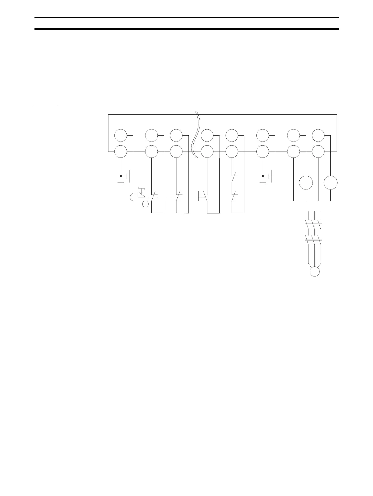
An example of the wiring and configuration when using the DST1-
XD0808SL-1 is shown below.
Wiring
V0
G0
IN0
T0
IN1
T1
IN6
→
11
12
21
22
S1
T2
S2
E1
IN7
T3
V1
G1 G1
KM2
E2
G1
KM1
OUT
1
OUT
0
KM1
-NC
KM2
-NC
M
KM1
KM2
GND
GND
E1, E2: 24-VDC power supply (S8@@)
S1: Emergency stop switch (A165E)
S2: Reset switch
KM1, KM2: Magnet contactor
M: 3-phase motor

 Loading...


