132
Examples of Wiring for Each Application Section 8-2
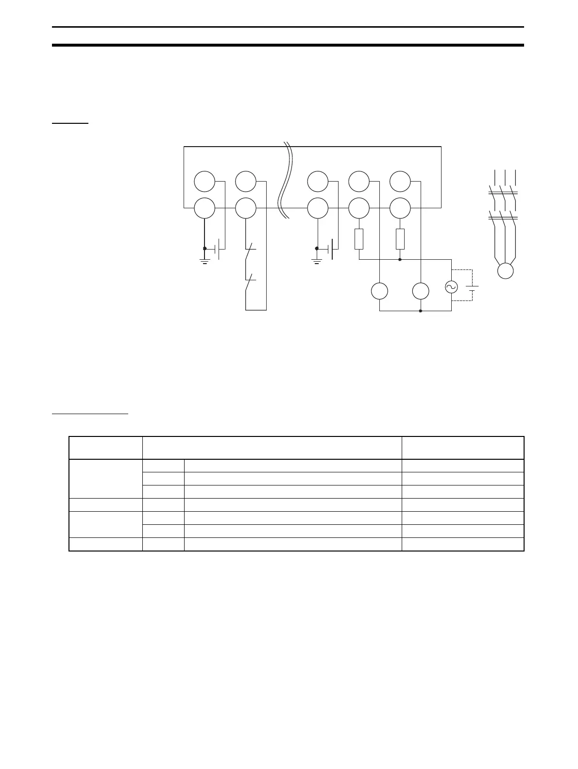
8-2-8 Relay Outputs with Dual Channel Mode and EDM Input
An example of the wiring and configuration when using the DST1-
MRD08SL-1 is shown below.
Wiring
Configuration
KM1
E1
E2
KM2
KM1
KM2
F1 F2
GNDGND
E1, E2: 24-V DC Power Supply (S8@@)
KM1, KM2: Magnetic Contactors
M: 3-phase motor
F1, F2: Fuses
KM1 KM2
M
V0 IN0 V1
OUT
1
OUT
0
G0 T0 G1 C1C0
Parameter
group
Parameter name Value
Safety Input 0 0015 Safety Input 0 Channel Mode Test pulse from test out
0016 Safety Input 0 Test Source Test Output 0
0029 Dual Channel Safety Input 0/1 Mode Single Channel
Test Output 0 0001 Test Output 0 Mode Pulse Test Output
Safety Output 0 0006 Safety Output 0 Channel Mode Used
0010 Dual Channel Safety Output 0/1 Mode Dual Channel
Safety Output 1 0007 Safety Output 1 Channel Mode Used

 Loading...


