15
Description of Safety Functions Section 1-4
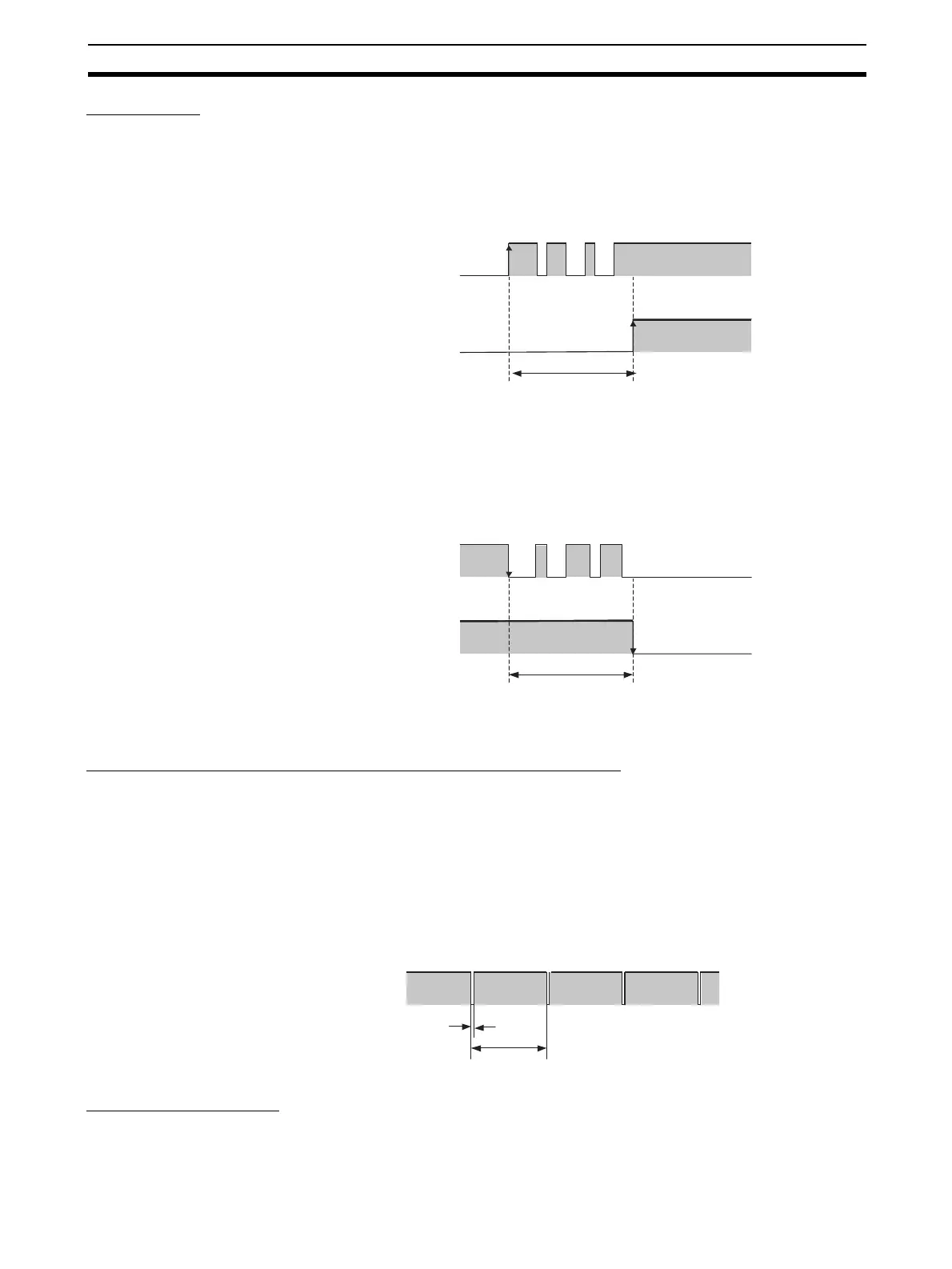
Input Delays
ON Delay
An input signal is treated as being OFF during the ON delay setting time (0 to
126 ms, in increments of 6 ms) after the input contact’s rising edge. The input
will turn ON only if the input contact remains ON after the ON delay time has
elapsed. This helps prevent chattering of the input contacts.
OFF Delay
An input signal is treated as being ON during the OFF delay setting time (0 to
126 ms, in increments of 6 ms) after the input contact’s falling edge. The input
will turn OFF only if the input contact remains OFF after the OFF delay time
has elapsed. This helps prevent chattering of the input contacts.
1-4-3 Safety Outputs
Safety Outputs with Test Pulses (Output Circuit Diagnosis)
When the output is ON, the test pulse is turned OFF for 580 µs in a cycle of
648 ms. Using this function, short-circuits between output signal lines and the
power supply (positive side) and short-circuits between output signal lines can
be detected.
If an error is detected, the safety output data and the individual safety output
status will turn OFF.
IMPORTANT To prevent the test pulse from causing the connected device to malfunction,
pay careful attention to the input response time of the device.
Dual Channel Setting
When both channels are normal, the outputs can be turned ON.
IN
ON
OFF
Remote I/O data
Safety input
ON
OFF
ON delay
IN
ON
OFF
Remote I/O data
Safety input
ON
OFF
OFF delay
OUT
ON
OFF
580 µs
648 ms

 Loading...


