16
Description of Safety Functions Section 1-4
The status is treated as normal when both channels are normal. If an error is
detected for one channel, the safety output data and the individual safety out-
put status will turn OFF for both channels.
Error Recovery
All conditions below are necessary to recover from an error that has occurred
in a safety output.
• The cause of the error must be removed.
• Error latch time must have passed.
• The output signals to the output I/O tags from the user application that
correspond to the safety output must go inactive.
1-4-4 I/O Status Data
In addition to I/O data, the DST1-series Safety I/O Terminals support status
data to check the I/O circuits. The status data includes the following data, for
which remote I/O communications can be performed.
• Normal Flags (ON when there is no faults in the internal circuit and the
external wiring)
• An AND Flag of the Normal Flags
• Output monitors (the actual output ON/OFF status)
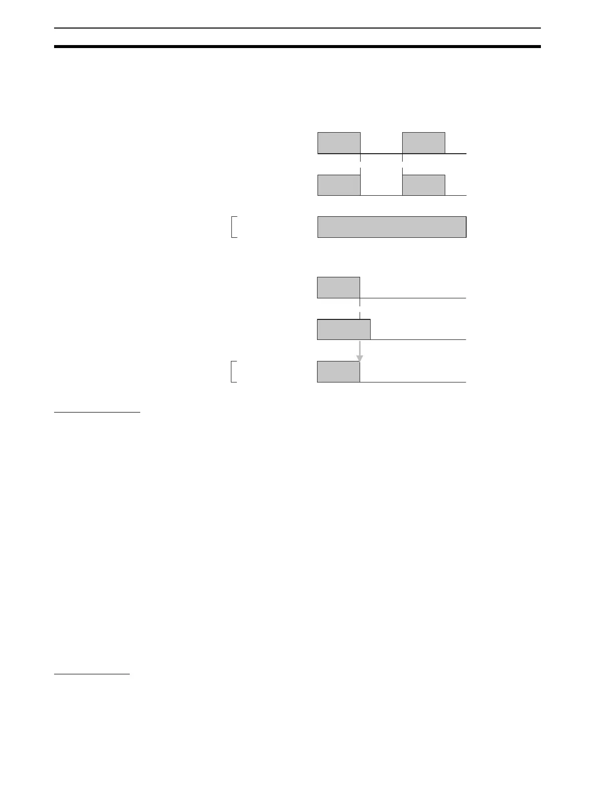
Normal Flags
Normal Flags indicates whether each safety input, safety output, or test output
is normal (normal status: ON, error status: OFF).
OUT0
ON
OFF
ON
OFF
Status of safety
outputs 0 and 1
ON
OFF
Remote
I/O data
OUT1
* Normal
OUT0
ON
OFF
ON
OFF
Status of safety
outputs 0 and 1
ON
OFF
Remote
I/O data
OUT1
Error
* Error

 Loading...


