125
Examples of Wiring for Each Application Section 8-2
8-2 Examples of Wiring for Each Application
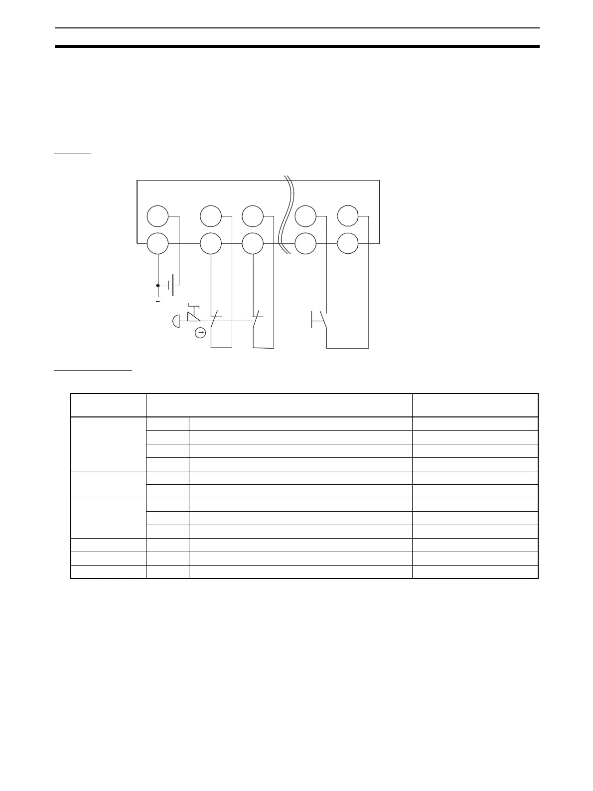
8-2-1 Emergency Stop Switch Dual Channel Inputs with Manual Reset
An example of the wiring and configuration when using the DST1-ID12SL-1 is
shown below.
Wiring
Configuration
11
12
21
22
S1 S2
E1
T2
G
GND
E1: 24-V DC Power Supply (S8@@)
S1: Emergency Stop Switch (A165E or
A22E) (positive opening mechanism)
S2: Reset switch
V
G
IN0
T0
IN1
T1
IN
11
T1
Parameter
group
Parameter name Value
Safety Input 0 0008 Safety Input 0 Channel Mode Test pulse from test out
0009 Safety Input 0 Test Source Test Output 0
0054 Dual Channel Safety Input 0/1 Mode Dual Channel Equivalent
0055 Dual Channel Safety Input 0/1 Discrepancy Time 100 x 10 ms
Safety Input 1 0012 Safety Input 1 Channel Mode Test pulse from test out
0013 Safety Input 1 Test Source Test Output 1
Safety Input 11 0052 Safety Input 11 Channel Mode Used as standard input
0053 Safety Input 11 Test Source Not Used
0064 Dual Channel Safety Input 10/11 Mode Single Channel
Test Output 0 0001 Test Output 0 Mode Pulse Test Output
Test Output 1 0002 Test Output 1 Mode Pulse Test Output
Test Output 2 0003 Test Output 2 Mode Power Supply Output

 Loading...


