126
Examples of Wiring for Each Application Section 8-2
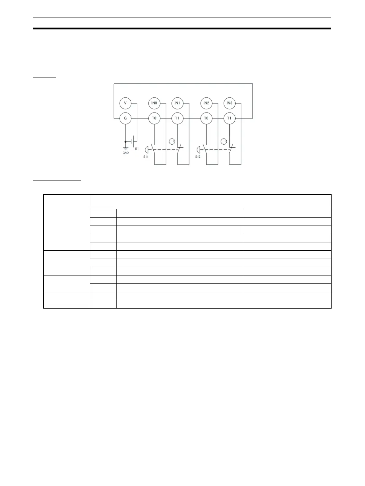
8-2-2 Two-Hand Input
An example of the wiring and configuration when using the DST1-ID12SL-1 is
shown below.
Wiring
Configuration
Note To connect switches, connect the NO terminals to input 0/2 and NC terminals
to input 1/3.
E1: 24-V DC Power Supply (S8@@)
S11,S12: Two-hand control switche
Parameter
group
Parameter name Value
Safety Input 0 0008 Safety Input 0 Channel Mode Test pulse from test out
0009 Safety Input 0 Test Source Test Output 0
0054 Dual Channel Safety Input 0/1 Mode Single channel
Safety Input 1 0012 Safety Input 1 Channel Mode Test pulse from test out
0013 Safety Input 1 Test Source Test Output 1
Safety Input 2 0016 Safety Input 2 Channel Mode Test pulse from test out
0017 Safety Input 2 Test Source Test Output 0
0056 Dual Channel Safety Input 2/3 Mode Single channel
Safety Input 3 0020 Safety Input 3 Channel Mode Test pulse from test out
0021 Safety Input 3 Test Source Test Output 1
Test Output 0 0001 Test Output 0 Mode Pulse Test Output
Test Output 1 0002 Test Output 1 Mode Pulse Test Output

 Loading...


