127
Examples of Wiring for Each Application Section 8-2
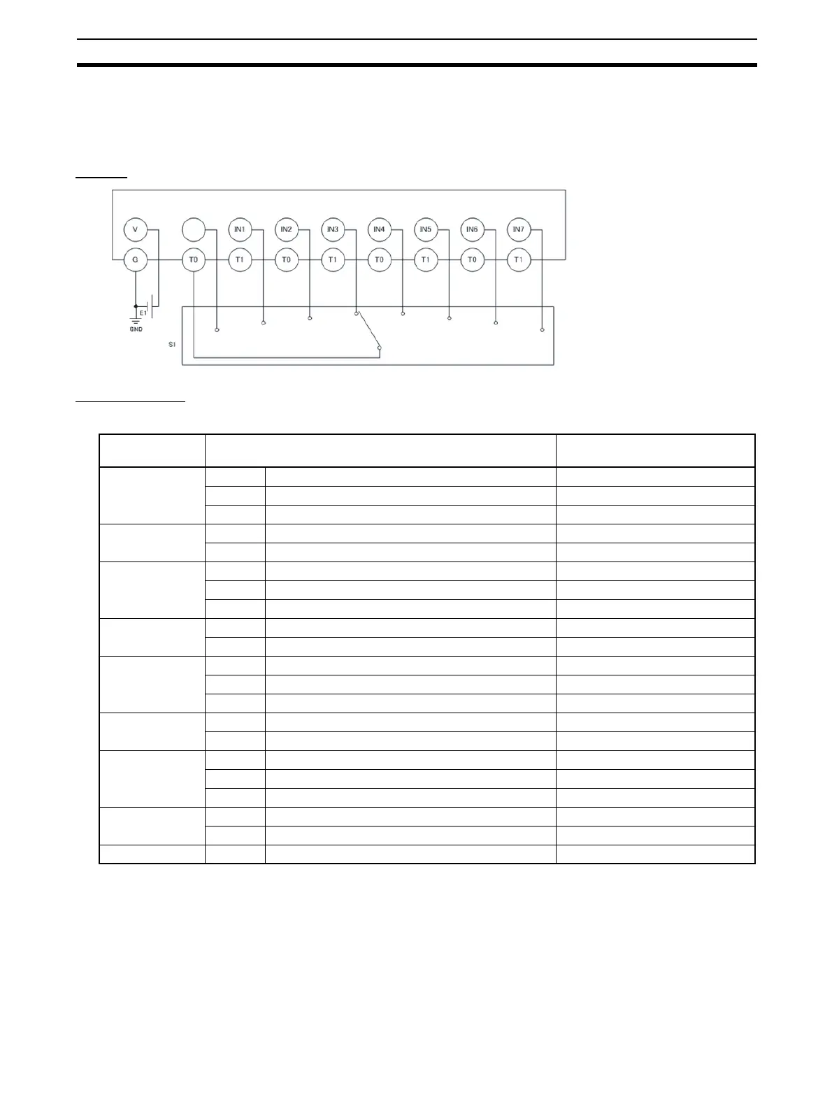
8-2-3 User Mode Switch Input
An example of the wiring and configuration when using the DST1-ID12SL-1 is
shown below.
Wiring
Configuration
E1: 24-V DC Power Supply
(S8@@)
S1: User mode switch
IN0
Parameter
group
Parameter name Value
Safety Input 0 0008 Safety Input 0 Channel Mode Test pulse from test out
0009 Safety Input 0 Test Source Test Output 0
0054 Dual Channel Safety Input 0/1 Mode Single Channel
Safety Input 1 0012 Safety Input 1 Channel Mode Test pulse from test out
0013 Safety Input 1 Test Source Test Output 0
Safety Input 2 0016 Safety Input 2 Channel Mode Test pulse from test out
0017 Safety Input 2 Test Source Test Output 0
0056 Dual Channel Safety Input 2/3 Mode Single Channel
Safety Input 3 0020 Safety Input 3 Channel Mode Test pulse from test out
0021 Safety Input 3 Test Source Test Output 0
Safety Input 4 0024 Safety Input 4 Channel Mode Test pulse from test out
0025 Safety Input 4 Test Source Test Output 0
0058 Dual Channel Safety Input 4/5 Mode Single Channel
Safety Input 5 0028 Safety Input 5 Channel Mode Test pulse from test out
0029 Safety Input 5 Test Source Test Output 0
Safety Input 6 0032 Safety Input 6 Channel Mode Test pulse from test out
0033 Safety Input 6 Test Source Test Output 0
0060 Dual Channel Safety Input 6/7 Mode Single Channel
Safety Input 7 0036 Safety Input 7 Channel Mode Test pulse from test out
0037 Safety Input 7 Test Source Test Output 0
Test Output 0 0001 Test Output 0 Mode Pulse Test Output

 Loading...


